SWT 3000 Equipment Manual PU3 Module
© SIEMENS AG 2008 Edition p3_3_x 08/09 Page - 9
Service interface
An RS232 service interface in the form of a 9-pole Sub-D socket is fitted at the PU3 for connect-
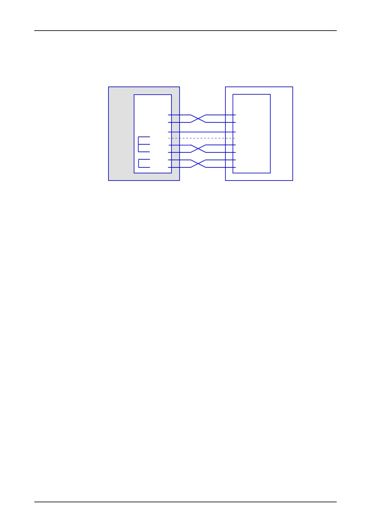
ing a service PC. The pin assignment is shown in the following drawing.
TD (3)
RD (2)
RTS (7)
CTS (8)
DSR (6)
SG (5)
DCD (1)
DTR (4)
PU PC
Schnittstelle
COMx
(3) TD
(2) RD
(5) SG
Verbindungskabel
(7) RTS
(8) CTS
(6) DSR
(1) DCD
(4) DTR
(9-pol.)
(9-pol.)
Frontplatte
Legend: Schnittstelle Frontplatte (9-Pol) Interface front panel (9-contact)
Verbindungskabel Connecting cable
Figure 5: in assignment of the RS232 service interface
The service interface is operated as a user interface with the "stand-alone" SWT 3000 unit and as
an internal interface to the CSP when the SWT 3000 is used in the PowerLink system (iSWT). The
selection is made through the device configuration.
Operating mode as stand-alone SWT 3000
The service interface is fed optionally to the Sub-D jack on the front panel or on the backplane.
A Busy detection circuit automatically switches over to the front panel interface if a PC is con-
nected there.
Operating mode as integrated SWT 3000 (iSWT)
In this operating mode the service interface is connected to the controller of the CSP module
(central signal processing) of the PowerLink unit via the LAN (local area network). The user service
interface is located on the CSP from where the parameters of the PU3f module are also set. The
plug on the front panel of the PU3f is not used and is covered.

 Loading...


