Functional Description SWT 3000 Equipment Manual
Page - 32 Edition p3_3_2x 08/09 © SIEMENS AG 2008
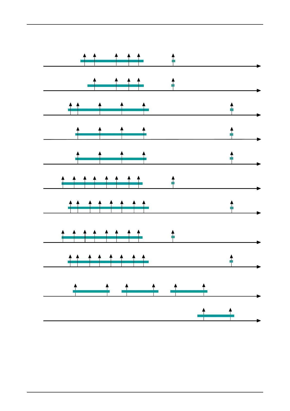
Frequency diagram for broadband and narrow band devices:
f7 f6 f5 f4 f3 f2 f1fs
fg
VF3_M5A
fg
VF1_M5A
0,67 0,89 1,11 1,34 1,56 1,78 2,00
3,81
2,61
f4fs
VF5
1,11
0,67 1,56
fg
3,81
2,00
f1f2
f4 fs
VF4
1,110,67 1,56
fg
3,81
2,00
f1 f2
f4
VF3
1,11 1,56
fg
3,81
2,00
f1f2fs
0,44 0,67
f3
fg
VF2
2,61
f4f3 f2 f1 fs fg
VF1
1,48 1,92 2,61
Mode 1 - 4
Mode 1
Mode 1 - 4
Mode 1
Mode 1
Mode 5A
Mode 5A
NB Ch1 NB Ch2 NB Ch3
NB Ch4
NB Ch1 - 3
NB Ch4
0,63 1,26 1,64 2,27 2,65 3,28
3,16 3,79
Mode 1 - 4
Mode 1 - 4
0,44
fs
f6 f5 f4 f3 f2 f1
0,365
0,58
0,81
1,03
1,25
1,475
1,70 1,92
f7
1,70
0,81
1,03
f4 f2 f1 fs
1,48 1,921,70
1,03
f7
f6
f5
f4
f3
f2
f1
fs fg
VF3_CT
f7
f6 f5 f4 f3 f2 f1 fs
fg
VF1_CT
0,67 0,89 1,11 1,34 1,56 1,78 2,00 3,81
0,365
0,58
0,81
1,03
1,25
1,475
1,70 1,92
2,61
0,44
fg Guard tone Mode 1-5 Operating modes 1 - 4
fs Clock synchronization NB Ch1-4 Narrow band channels 1-4
M5A Operating Mode M5A
VFx_CT Frequencies for coded tripping used for operating Mode 1, 2, 3a, 3b, 4
Mode 1, 2 or 4 can be transmitted coded or non coded
Figure 13: Frequency diagram for broadband and narrow band devices

 Loading...


