SWT 3000 Equipment Manual Installation and Commissioning
Equipment of the sub rack without FOM slots
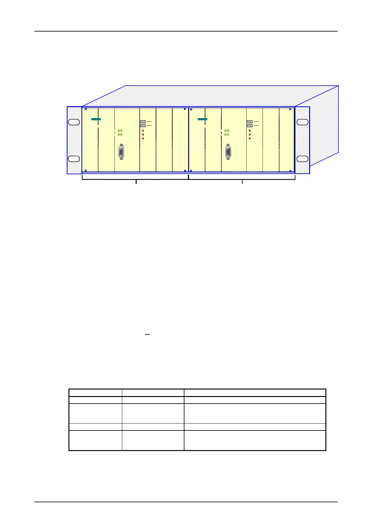
A maximum of two SWT 3000 devices can be installed in an ES902 sub rack. These devices form
two separately operating systems each with its own power supply.
LID1
LIA
SAL
EAL
S/N
>
>
IFC_2 IFC_1 PU3_1 CLE_1 ALRS_1 SV_1
LID1
LIA
SAL
EAL
S/N
>
>
IFC_4 IFC_3 PU3_2 CLE_2 ALRS_2 SV_2
SIEMENS
SWT 3000
LID2
OK
SIEMENS
LID2
OK
SWT 3000
System 1 System 2
IFC_1 Slot 1 IFC-x in device 1 IFC_3 Slot 1 IFC-x in device 2
IFC_2 Slot 2 IFC-x in device 1 IFC_4 Slot 2 IFC-x in device 2
PU3f_1 Processor module, device 1 PU3f_2 Processor module, device 2
CLE_1 Copper line equipment, device 1 CLE_2 Copper line equipment, device 2
(only with analog interface) (only with analog interface)
ALRS_1 Alarm module, device 1 ALRS_2 Alarm module, device 2
SV_1 Power supply, device 1 SV_2 Power supply, device 2
Figure 2: Equipment of the sub rack with two SWT 3000 systems
Equipment of the IFC slots
IFC_1and IFC_3 Slots IFC_1 (in device 1) and IFC_3 (in device 2) must be equipped with
an interface module IFC-D (direct tripping) or IFC-P (permissive tripping).
The commands to be transmitted by the protective relay are also con-
nected here (binary inputs 1-4). Output of the received commands to the
protective relay is also via these modules.
IFC_2 and IFC_4 An additional slot IFC_2 (in device 1) and IFC_4 (in device 2) is available
in every device for an IFC module. This can be equipped with types
IFC-D
, IFC-P or IFC-S (signaling).
If this slot is equipped with an IFC-D or IFC-P the output relays of these
modules are used for doubling the contacts. The inputs are not used. If it
is equipped with an IFC-S module this is used for signaling commands
that are entered (binary inputs) or output (relay outputs) by modules
IFC-D or IFC-P at slot 2.
Table 2: Equipment options for slots IFC_1 to IFC_4
Slot Equipment Application
IFC_1 IFC-D and IFC-P Device 1 command input/command output
IFC_2 IFC-D, IFC-P or IFC-S Device 1 doubling of command output contacts or
status messages slot IFC./1. Command in-
put/command output only with digital interfaces.
IFC_3 IFC-D and IFC-P Device 2 command input/command output
IFC_4 IFC-D, IFC-P or IFC-S Device 2 doubling of command output contacts or
status messages slot IFC./3. Command in-
put/command output only with digital interfaces.
The terminal assignment of the modules is shown in Figure 5.
© SIEMENS AG 2008 Edition p3_3_2x 08/09 Page - 9

 Loading...


