PU3 Module SWT 3000 Equipment Manual
Page - 8 Edition p3_3_2x 08/09 © SIEMENS AG 2008
Significance of the LEDs on the PU3
z The 2-color LED LIA is needed for displaying the status of the analog line interface
LIA. The following states can be displayed:
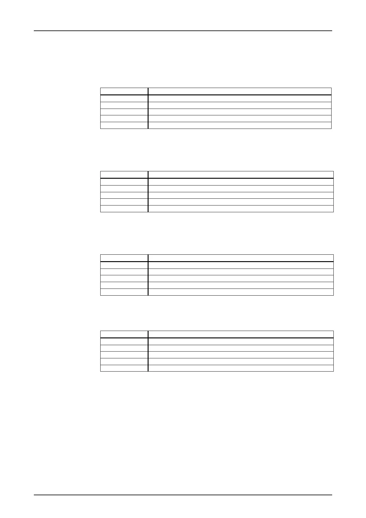
Table 1: Significance of the LED LIA displays
State Significance
off LIA not configured
red static LIA is not ready for operation
red flashing LIA is only operational to a limited extent (e.g. receive alarm)
green static LIA functioning correctly
green flashing Test operation or secondary path
z The 2-color LED LID-1 is used for displaying the status of the digital line interface
LID-1. The following states can be displayed:
Table 2: Significance of the LED LID-1 displays
State Significance
off LID-1 not configured
red static LID-1 is not ready for operation
red flashing LID-1 is only operational to a limited extent (e.g. receive alarm)
green static LID-1 functioning correctly
green flashing Test operation or secondary path
z The 2-color LED LID-2 is used for displaying the status of the digital line interface
LID-2. The following states can be displayed:
Table 3: Significance of the LED LID-2 displays
State Significance
off LID-2 not configured
red static LID-2 is not ready for operation
red flashing LID-2 is only operational to a limited extent (e.g. receive alarm)
green static LID-2 functioning correctly
green flashing Test operation or secondary path
z The 2-color LED OK/BGAL is needed for displaying the PU3 module status. The fol-
lowing states can be displayed:
Table 4: Significance of the LED OK/BGAL displays
State Significance
off Power Supply disconnected or faulty
red static Module is not ready for operation
red flashing General alarm module is only operational to a limited extent
green static Normal operation
green flashing Test operation

 Loading...


