ALRS and ALR Module SWT 3000 Equipment Manual
Page - 8 Edition p3_3_2x 08/09 © SIEMENS AG 2008
Binary inputs
The module ALR provides two electrically isolated inputs BI1 and BI2 with selectable input voltage
levels. As the circuits for the binary inputs comprise rectification, differential DC input signals of ei-
ther polarity can be connected. The output signals of the circuits have TTL level. Binary input BI1 is
alternatively configurable as an input for entering IRIG-B signals.
Relay outputs
The alarm module comprises as well three alarm outputs, switched by relay (K1 – K3). The three
relays provide change over contacts. In the standard setup the break contacts (NC) are used.
X17 X16
X15X14
X7 X6 X5
X10
X9
X8
X13
X11
X12
H1
H3
H2
H6
H5
H4
K1
K2
K3
X4
X2
X3
S1
1
1
2
3
4
5
68
79
10
1
2
3
4
5
68
79
10
1
2
3
4
5
6
12
34
56
X1 8
BI1/USYNC
SLOW
FAST
12
34
56
X1 9
SLOW
FAST
IRIG B
BI1/USYNC
BI2
1
1
0
V
4
8
/
6
0
V
2
4
V
2
5
0
V
P
a
r
k
1
1
0
V
4
8
/
6
0
V
2
4
V
P
a
r
k
2
5
0
V
5
V
1
2
V
2
4
V
ALA3
ALA1
ALA2
IRIG-B
BI1
BI2
ALA1
ALA2
ALA3
Test BI2
Test BI1
Test IRIG-B
n.u.
BI2
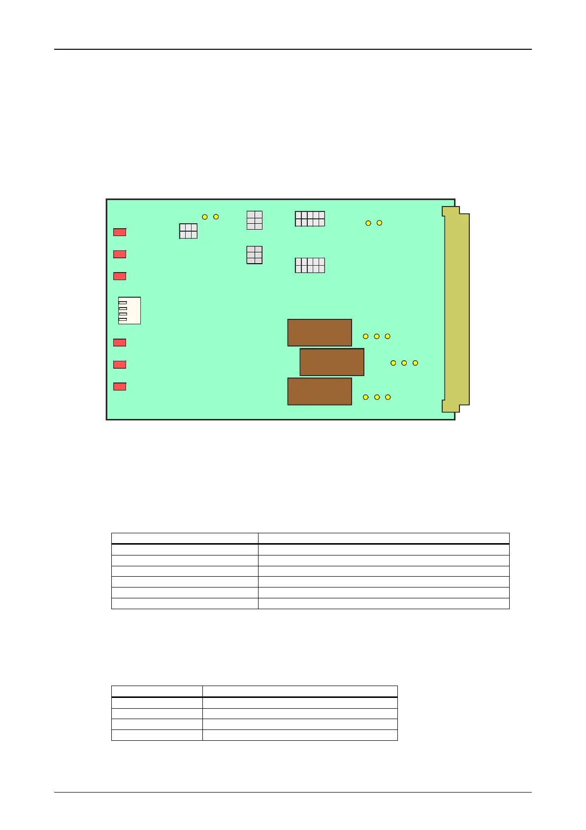
Figure 5: Display and setting elements on the ALR module
Visual Indication
The module ALR provides a LED for visual indication of the state for each binary input and for
each alarm output. They are visible after removal of the front panel. The significations are shown in
the table below:
Table 4: ALR indication
LED Indication
H6 IRIG-B Input energized
H5 Binary Input 1 energized
H4 Binary input 2 energized
H3 Alarm output 1 activated
H2 Alarm output 2 activated
H1 Alarm output 3 activated
Test switch S1
For test purposes the module ALR provides a switch for each of the binary input circuits and for
the IRIG-B circuit. Closing a switch sets the output of the assigned circuit to the active state.
Table 5: Functions of the ALR test switch
Switch Function
S1.1 Binary Input 2 test
S1.2 Binary input 1 test
S1.3 n.u.
S1.4 IRIG-B test

 Loading...


