CLE Module SWT 3000 Equipment Manual
Page - 6 Edition p3_3_x 08/09 © SIEMENS AG 2008
S6 control wires
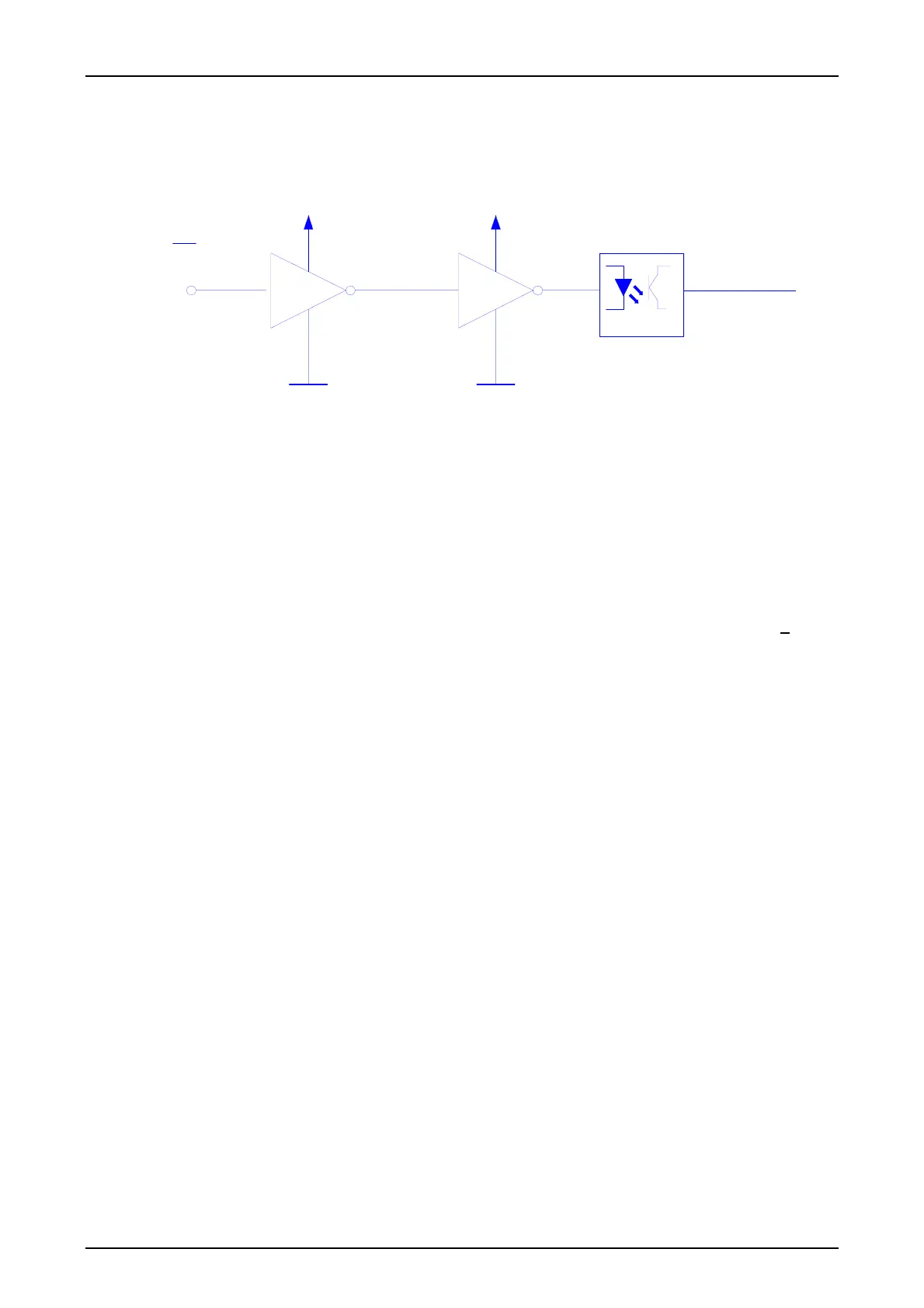
The CLE module contains an opt coupler for the S6 control wire. The S6 control wire is used for
disconnecting voice and data signals in a PLC system in alternate multi-purpose mode.
+12 V+5 V
S6
b23
S6
Figure 5: Block diagram of the S6 control
The circuit is driven on a low-active basis. The opt coupler is activated during transmission of pro-
tection data (S6 control wire =low).
Test sockets
The following test sockets are provided on the front panel of the CLE module:
z 1 ISEP socket for measuring the level of the receive signal
z 1 ISEP socket for measuring the level of the transmit signal
The level at the sockets is measured on a high impedance basis and corresponds to the value at
the measuring point. Incorrect operations such as short circuiting or inserting a signal (U <
5V) at
the measuring sockets does not result in interruption of teleprotection signaling.
Inhibit line
An inhibit line is routed via the CLE module which acts on the inhibit input of the power supply. If
there is no CLE module (in the case of a device with digital interfaces only) link X41 must therefore
be inserted in position 1-2 in the sub rack.

 Loading...


