SWT 3000 Equipment Manual ALRS and ALR Module
© SIEMENS AG 2008 Edition p3_3_2x 08/09 Page - 5
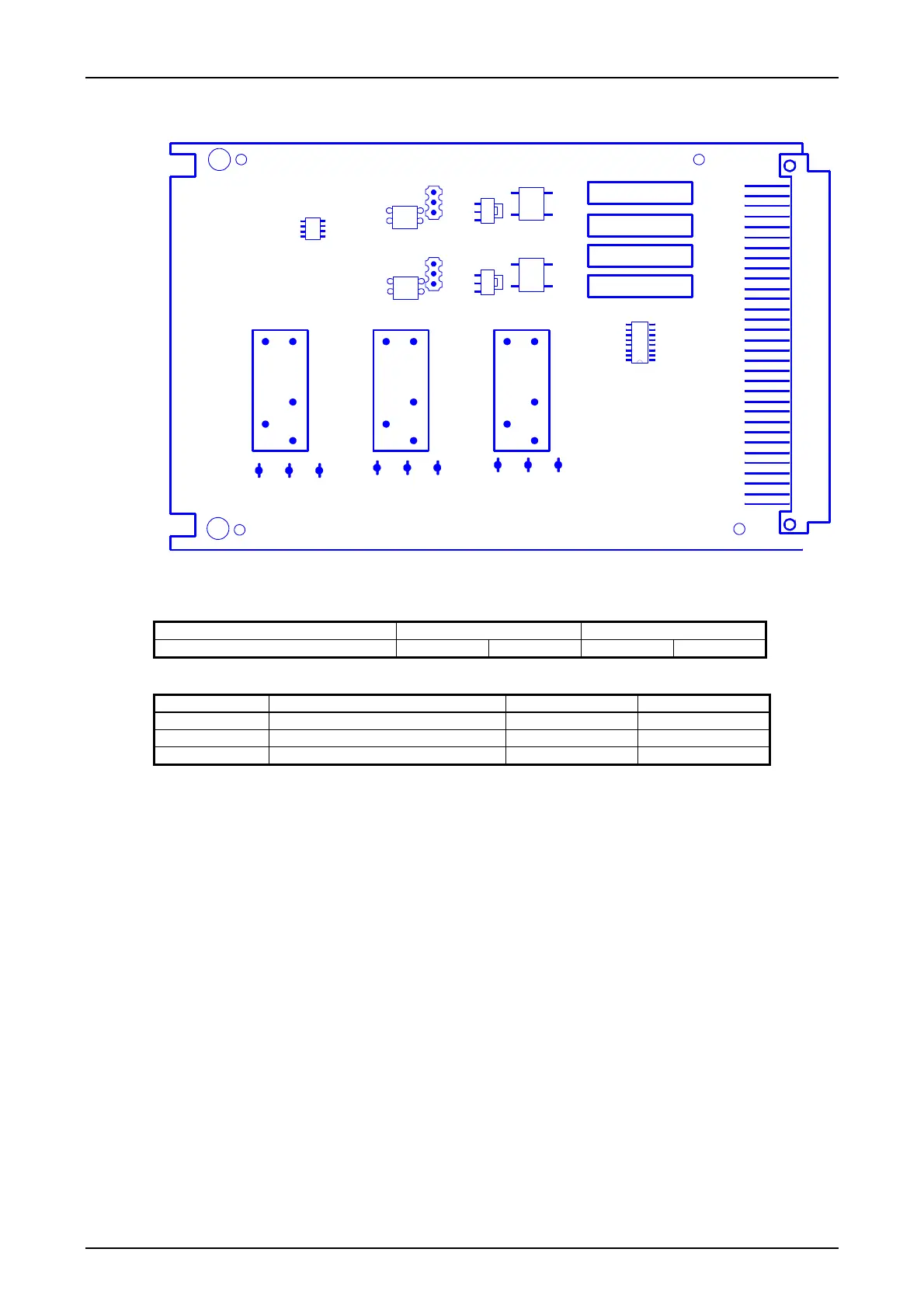
Jumper settings
K2
K3
K1
X4
X5X6 X7X8X9
X10X11X12
R17
R16
R8
R7
X3
1
X2
1
N2
V8
V4
V7
V3
U2
U1
N1
X1
Figure 3: Position of the jumper on the ALRS
Table 1: Selection of the operating point for the ALRS input
Input Input voltage 15 V – 250V Input voltage 54V – 250V
Clock synchronization Link X3 1 - 2 Link X3 2 - 3
Table 2: Selection of the relay contacts of the ALRS outputs
Alarm relay Designation Break contact (NC) Make contact (NO)
K1 General alarm X4 - X5 X5 - X6
K2 Pre- alarm X7 - X8 X8 - X9
K3 Receiver alarm X10 - X11 X11 - X12

 Loading...


