SWT 3000 Equipment Manual Installation and Commissioning
Jumper settings for the PU3f module
X14
X15
X16
S1
H1
H2
X10
X9
X6
X7
X8
X1
X17
X3
X13
1
1
26
1
26
1
34
1
9
1
Power ON / OFF
Connection of the IFC
modules
Connection of the DLE
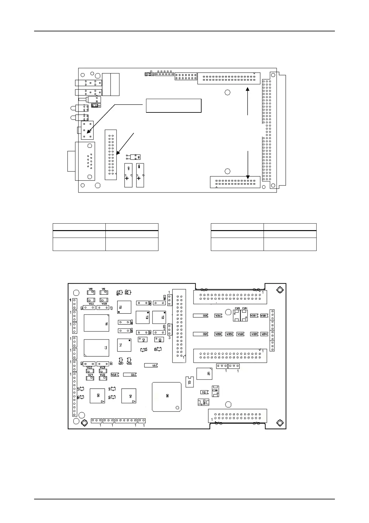
Figure 9: Position of the jumpers on the PU3f module
Table 20: Function of the jumpers on the PU3f module
Jumper X16 Function Jumper X17 Function
1-2 Normal operation 1-2 Normal operation
2-3 Monitor operation 2-3 Programming with
Memtool
When using digital line interfaces links must be set on the DLE module. Module DLE is designed
as a self-contained PC board that is connected electrically to the PU3 via a ribbon cable and me-
chanically via spacer sleeves. All external interfaces are routed via the PU3f module.
X52
X53
X3 X45
X4
X5
X42
X46
X9
X8
X47
X7
X6
X49
X44 X43
X48
X10
X11
X20
X21
X22
X23
1
1
1
1
Figure 10: Position of the jumpers on the DLE module
© SIEMENS AG 2008 Edition p3_3_2x 08/09 Page - 21

 Loading...


