110 MS 201, MS 201 C, MS 201 T, MS 201 TC
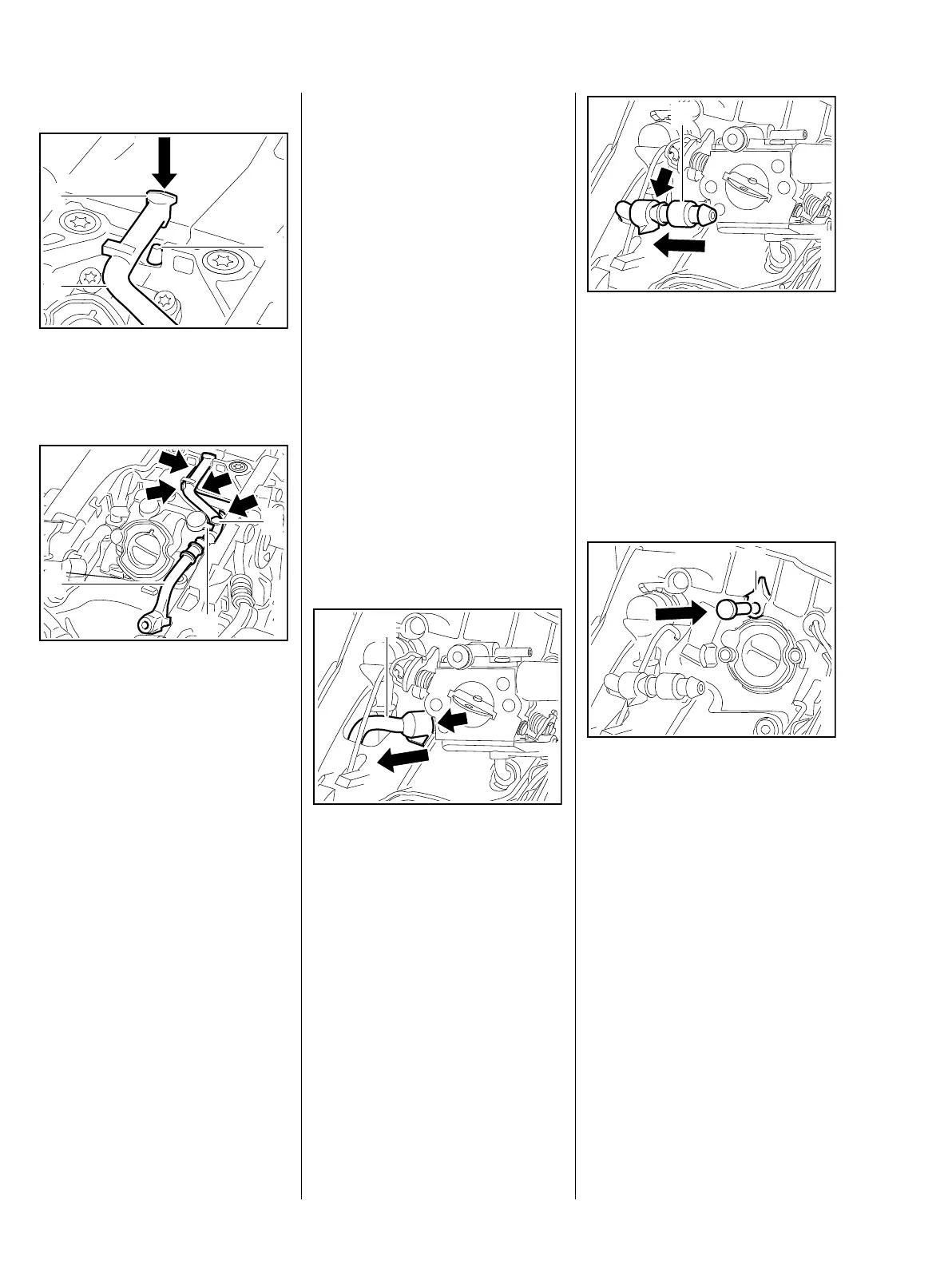
Installing
: Push impulse hose (1) with
elbow connector (2) fully onto the
nipple (3).
: Position the impulse hose (1) in
the guides (arrows) and push it
home until the lug (2) is on top of
the hose (1).
The lug (2) must locate against the
knob (3).
– Fit the handle housing
MS 201, b 10.4
MS 201 T, b 10.5
– Install the carburetor.
MS 201 b 12.4,
MS 201 T b 12.5
– Reassemble all other parts in the
reverse sequence.
7013RA261 TG
1
2
3
7013RA262 TG
1
2
3
12.9 Tank Vent
12.9.1 Testing
If problems occur on the carburetor
or the fuel supply system, also
check and clean the tank vent and
replace it if necessary. Check
function by performing pressure and
vacuum tests on the tank via the fuel
suction hose.
The following preparations describe
the MS 201, but also apply to the
MS 201 T.
– Open the fuel tank cap and drain
the fuel tank.
– Collect the fuel in a clean
container, b 1
– Close the tank cap.
– Remove the air filter, b 12.1
: Pull the fuel suction hose (1) off
the stub (arrow).
7013RA263 TG
1
: Push the nipple (1)
0000 855 9200 into the fuel
suction hose (arrow).
Models with manual fuel pump
– Remove the carburetor,
MS 201 b 12.4,
MS 201 T b 12.5
: Use a suitable plug to seal the
fuel hose (1).
7013RA264 TG
1
7013RA462 TG
1
 Loading...