54 MS 201, MS 201 C, MS 201 T, MS 201 TC
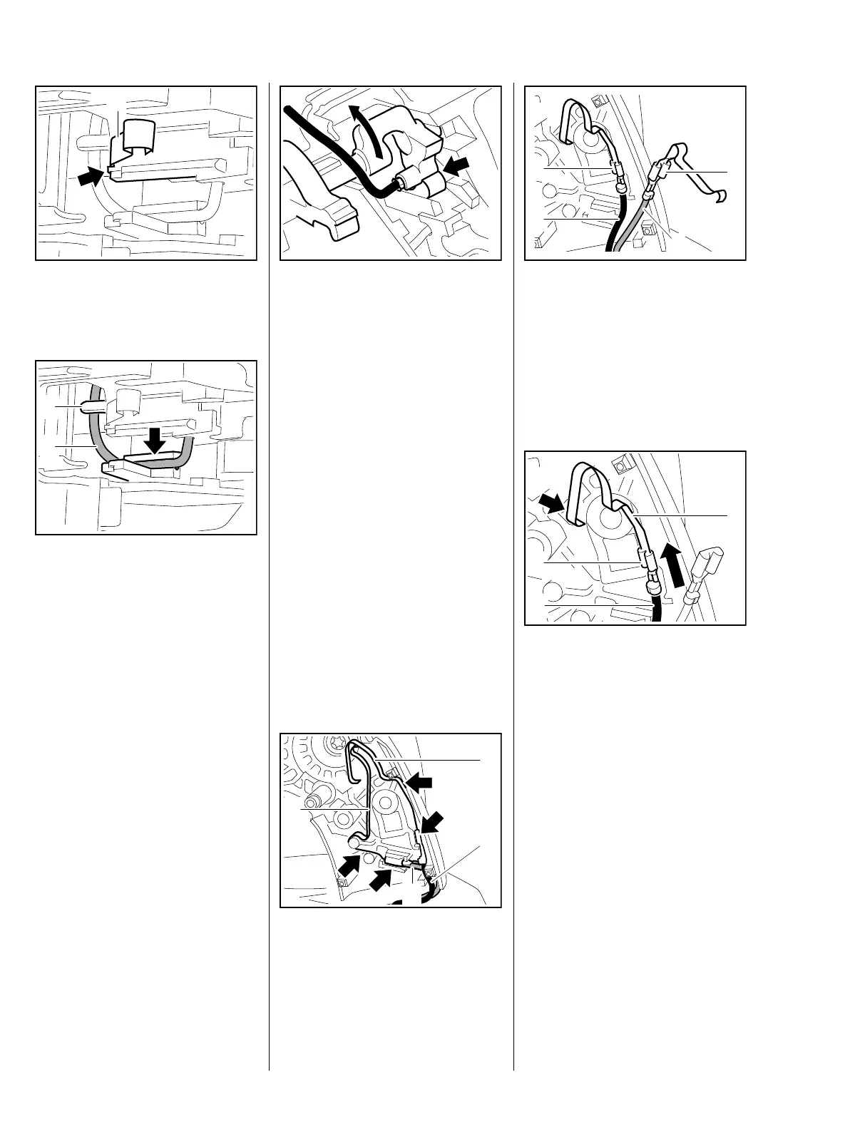
The contact spring (1) must be
completely behind the lateral guide
(arrow).
Fit ground wire (1) in the guide (2).
: Use punch-down tool
5910 890 4000 to press the
ground wire (1) fully into the
guide (arrow).
– Install switch shaft with short
circuit wire attached, b 10.1.1
7013RA443 TG
1
7013RA444 TG
2
1
: Check operation
– short circuit wire's connector
sleeve must touch the contact
spring (arrow) in position "0".
– Reassemble all other parts in the
reverse sequence.
7.6.6 Contact Springs
(MS 201 T)
The ground wire must be firmly
seated on the contact spring,
perform contact and continuity test if
necessary, b 7.6.1.
– Remove the lockout lever and
throttle trigger, b 10.3
– Remove the switch shaft,
b 10.1.2
– Remove the AV spring, b 9.2.1
: Pull contact spring (1) of short
circuit wire (2) and contact
spring (3) of ground wire (4) out
of guides (arrows).
7013RA209 TG
4
7013RA296 TG
1
2
3
: Disconnect terminal (1) of short
circuit wire (2) and terminal (3) of
ground wire (4).
– Inspect the contact springs and
replace if necessary,
Installing
: Push the terminal (1) of short
circuit wire (2) onto the contact
spring (3) so that the crimped
side faces the spring loop (arrow)
– narrow terminal on narrow
contact spring.
7013RA445 TG
1
2
3
4
7013RA446 TG
1
2
3
 Loading...