91MS 201, MS 201 C, MS 201 T, MS 201 TC
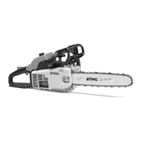
MS 201 T
: Push on the grommet (3) as far
as stop and fit tab (4) under the
oil pump's shoulder.
: Place the oil pump (1) in position
and turn it counterclockwise until
the stub (arrow) is properly
seated in the connector's
bore (2).
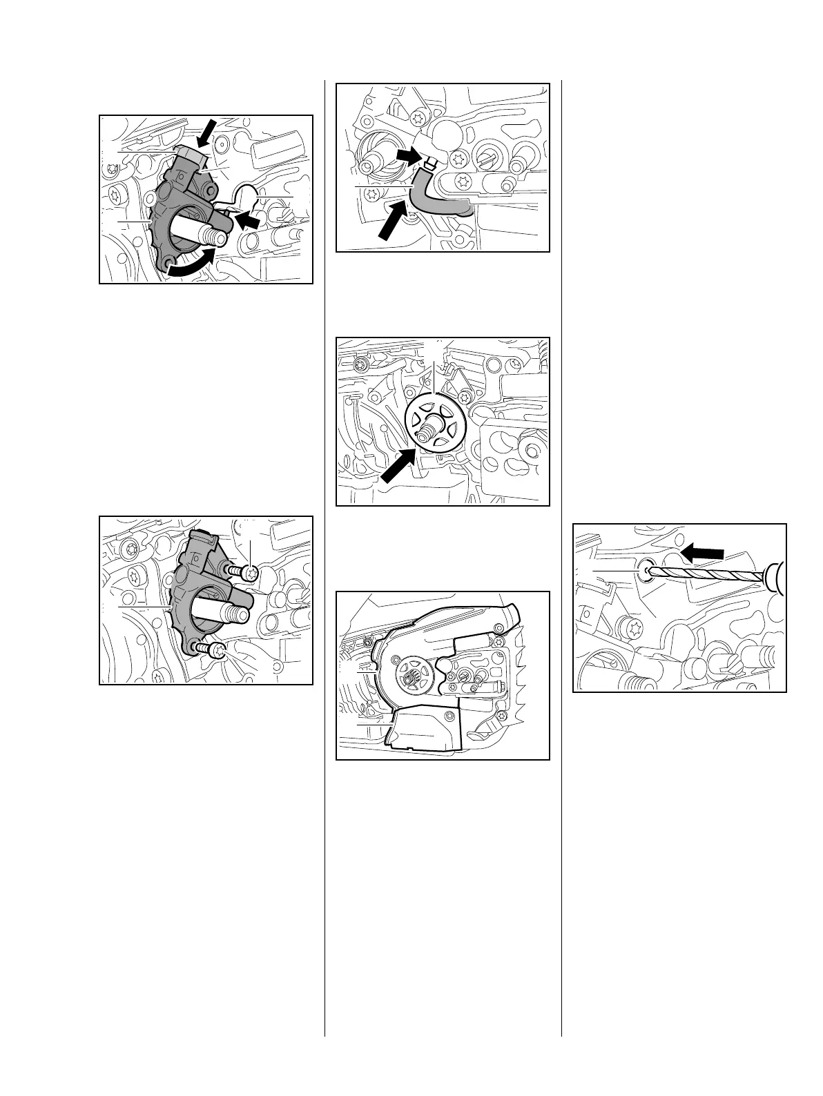
All models
: Line up the oil pump (1) with the
holes.
: Insert and tighten down the
screws (2) firmly.
7013RA528 TG
1
3
2
4
7013RA104 TG
1
2
2
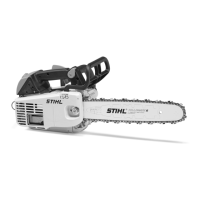
: Push the oil suction hose (1) onto
the oil pump's stub (arrow).
: Push the worm (1) into the oil
pump.
: Place the cover (1) in position.
: Slide cover (2) into cover (1) first,
then press the underside into the
crankcase until it snaps into
place.
– Fit the screws and tighten them
down firmly.
– Reassemble all other parts in the
reverse sequence.
7013RA105 TG
1
7013RA106 TG
1
7013RA107 TG
1
2
11.5 Valve
A valve is installed in the housing
wall to keep internal tank pressure
equal to atmospheric pressure. The
valve must be replaced if it is faulty.
– Open the oil tank cap and drain
the oil tank.
– Collect chain oil in a clean
container, b 1
– Disengage the chain brake and
remove the chain sprocket cover,
bar and chain.
– Remove the clutch drum, b 4.2
– Remove the cover, b 11.4
The valve has to be pulled out, e.g.
with sleeve 1127 791 7200,
M 4 x 25 mm screw and M 4 nut.
Drill to a depth of no more than
5mm
– no deeper, otherwise the ball,
spring and washer will fall into the
oil tank.
: Drill valve (1) to 3.3 mm diameter
and cut an M 4 thread.
– Clean away drillings. Remove
ball, spring and washer from
inside oil tank if necessary.
7013RA513 TG
1
 Loading...