78 MS 201, MS 201 C, MS 201 T, MS 201 TC
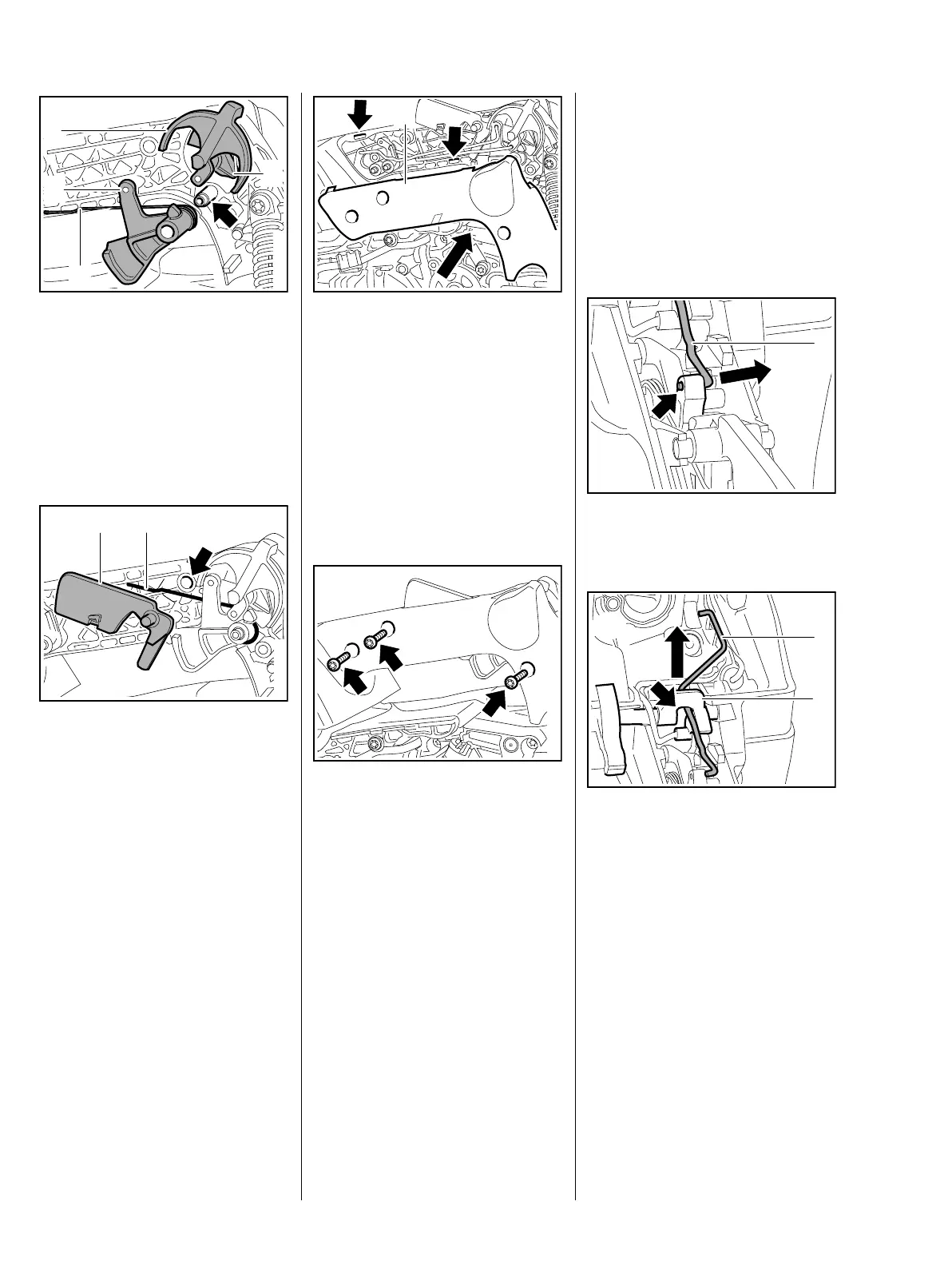
: Turn the switch shaft (1) so that
the throttle trigger (2) can be
maneuvered past the cam (3).
: Push the throttle trigger (2) onto
the pivot pin (arrow) so that the
leg (4) of the torsion spring is
behind the trigger (2).
: Attach the lockout lever (1) to the
torsion spring (2).
: Push the lockout lever (1) with
torsion spring into the bore
(arrow).
7013RA229 TG
1
3
2
4
7013RA230 TG
2
1
– Install the throttle and choke
rods, b 10.3.2
: Position the handle molding (1)
so that the lugs engage the seats
(arrows).
: Carefully push the handle
molding (1) into place – the
throttle trigger and lockout lever
may pop out.
: Insert the screws (arrows) and
tighten them down firmly.
– Check operation
– Throttle trigger must be
blocked when the lockout lever is
not operated and the switch lever
must be blocked in the direction
of cold start when the throttle
trigger is not operated.
– Reassemble all other parts in the
reverse sequence.
1
7013RA231 TG7013RA232 TG
10.3.1 Choke and Throttle Rods
(MS 201)
– Remove the handle molding,
b 10.2
– Remove the carburetor and put it
to one side, b 12.4
: Disconnect throttle rod (1) from
hole (arrow) in throttle trigger.
: Pull throttle rod (1) out through
the switch shaft (1) (arrow) and
lift it away.
7013RA233 TG
1
7013RA234 TG
1
2
 Loading...