46 MS 201, MS 201 C, MS 201 T, MS 201 TC
While using the ZAT 3, hold it only
by the handle (4) or position it in a
safe place. Keep fingers or other
parts of your body at least 1 cm
away from the spark window (3),
high voltage connection (2), ground
connection (5) and the ground
terminal (1).
High voltage – risk of electric shock.
– Crank the engine quickly with the
rewind starter and check spark in
the tester’s window (3).
The engine may start and
accelerate during the test.
If a spark is visible in the
window (3), the ignition system is in
order.
– If no spark is visible in the
window (3), check the ignition
system with the aid of the
troubleshooting chart, b 7.7
165RA185 TG
1
2
3 4
5
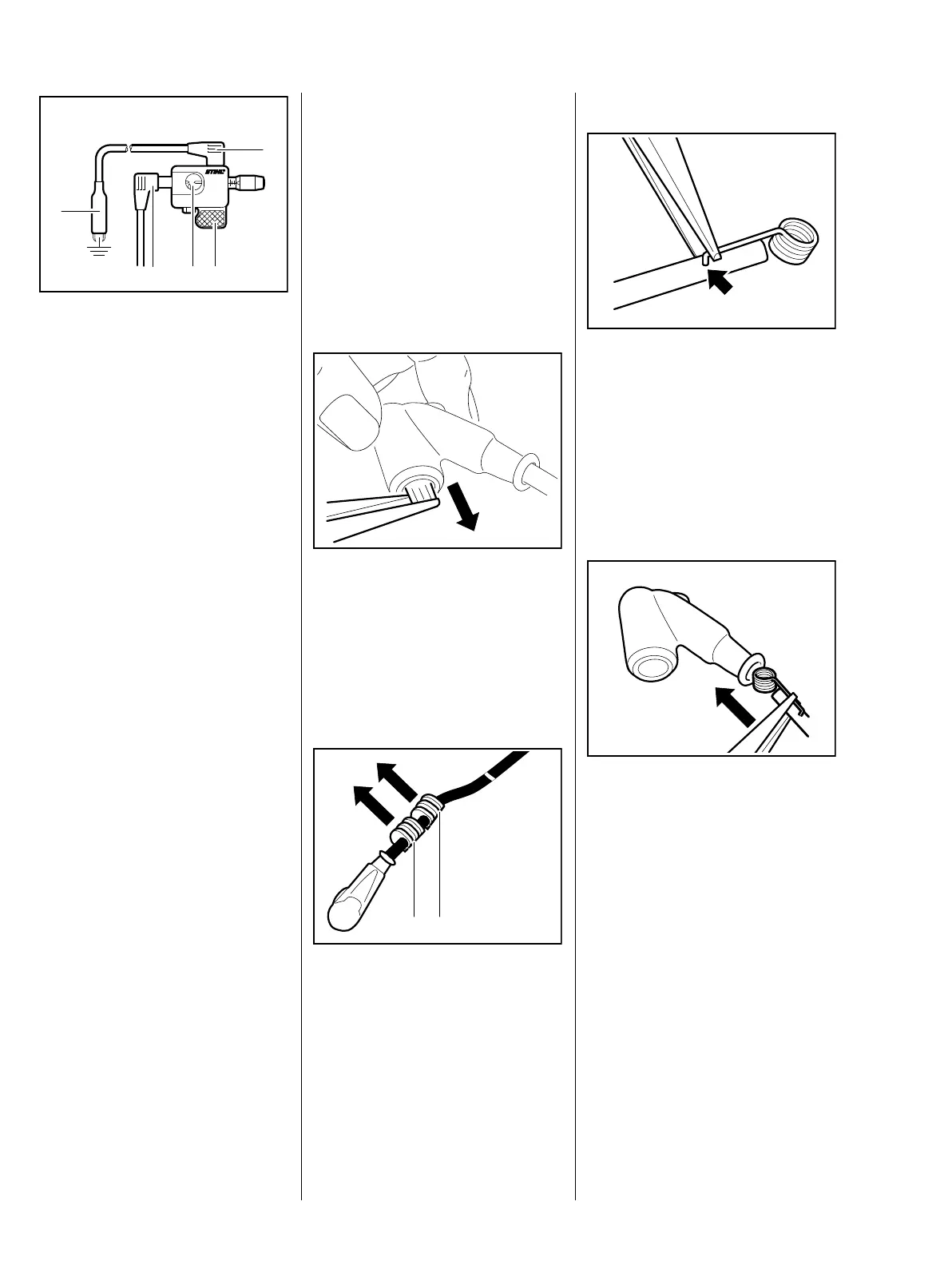
7.4 Spark Plug Boot /
Ignition Lead
The ignition module (1) and ignition
lead (2) form a unit. A new ignition
module must be installed if the
ignition lead is damaged.
– Remove the fan housing, b 8.2
– Pull the boot off the spark plug.
: Use suitable pliers to pull the leg
spring out of the spark plug boot.
– Unhook the leg spring from the
ignition lead.
– Pull the boot off the ignition lead.
: Pull the two retainers (1) off the
ignition lead.
– Check ignition lead, replace
ignition module if necessary,
b 7.2
2310RA127 TG7013RA383 TG
1 1
Installing
– If the ignition module is new, use
a pointed tool to pierce the center
of the ignition lead’s insulation,
about 15 mm from the end of the
lead.
: Pinch the hook of the leg spring
into the pierced hole in the center
of the lead (arrow).
– Coat the inside of the spark plug
boot with STIHL press fluid,
b 14
: Hold the ignition lead and leg
spring together and push them
into the spark plug boot.
165RA188 TG
2310RA128 TG
 Loading...