68 MS 201, MS 201 C, MS 201 T, MS 201 TC
Installing
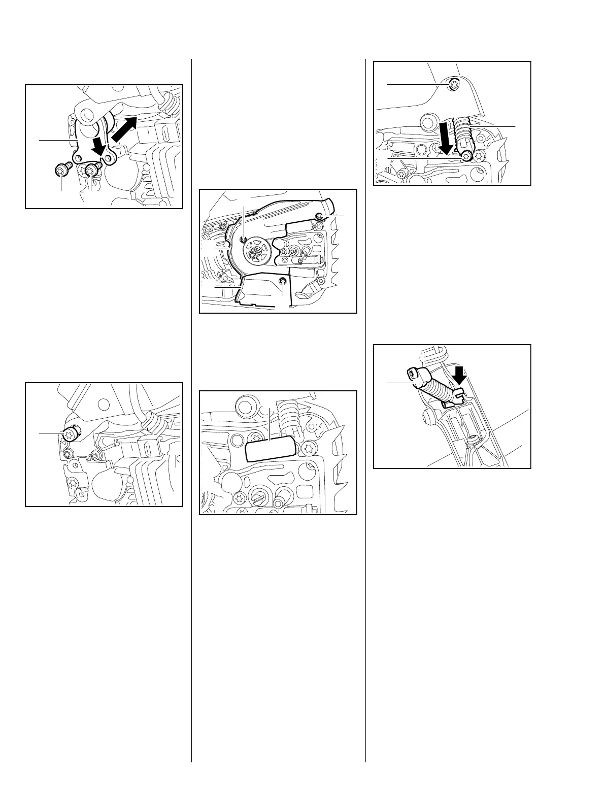
: Line up the rubber buffer (1) so
that it faces the handle housing –
the notch (arrow) must engage
the lug on the tank housing.
: Push the buffer (1) into position
between the handle housing and
crankcase.
: Insert and tighten down the
screws (2) firmly.
: Insert screw (1) through lug on
handle housing and into the
annular buffer.
: Insert and tighten down the
screw (1) firmly.
– Reassemble all other parts in the
reverse sequence.
2
7013RA189 TG
2
1
7013RA190 TG
1
9.2 AV Spring on Oil Tank
(MS 201)
– Disengage the chain brake and
remove the chain sprocket cover,
bar and chain.
– Remove the clutch drum, b 4.2
: Take out the screws (1).
: Remove covers (2) and (3).
: Pry out the bumper strip (1).
7013RA191 TG
1
1
1
2
3
7013RA192 TG
1
: Take out screws (1) and (2) –
screw (2) is secured with Loctite;
it may be necessary preheat it
with a hot air blower.
: Pull the AV spring (3) out of the
handle housing, inspect it and
replace if necessary.
Installing
: Position the AV spring (1) so that
the lug (arrow) points in the
direction of the handle housing.
The lug (arrow) holds the short
circuit and ground wires in the
handle housing's guide.
7013RA193 TG
2
1
3
7013RA194 TG
1
 Loading...