67MS 201, MS 201 C, MS 201 T, MS 201 TC
9. AV Elements
Vibration-damping springs, annular
buffers and stop buffers are used for
the connection between the
handlebar, tank housing and
crankcase.
Damaged springs, annular buffers
and stop buffers must always be
replaced.
9.1 Annular Buffer on Fuel
Tank (MS 201)
– Disengage the chain brake and
remove the chain sprocket cover,
bar and chain.
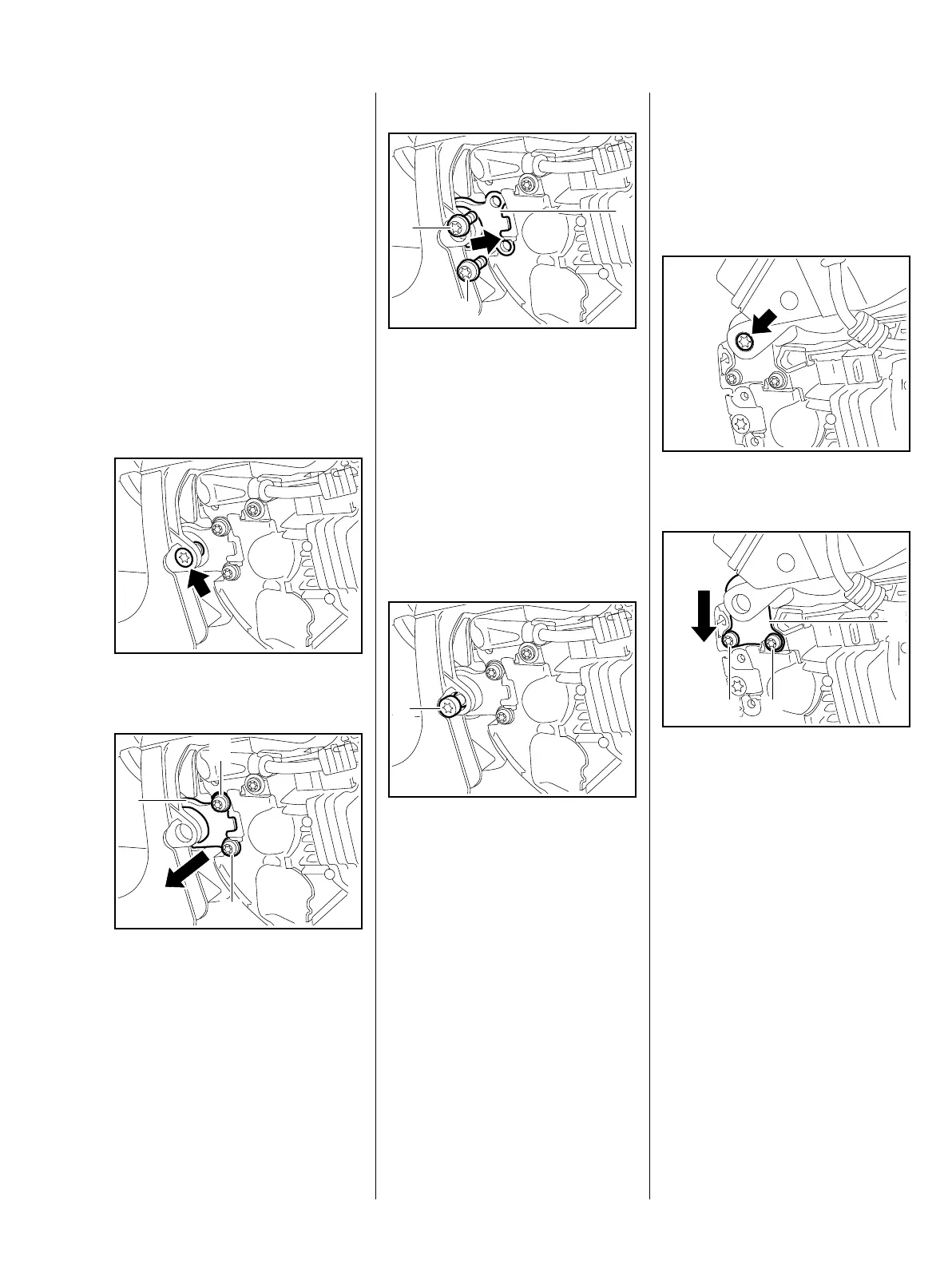
: Take out the screw (arrow).
: Take out the screws (1).
: Pull the annular buffer (2) out of
the recess, inspect it and replace
if necessary.
7013RA183 TG
2
1
1
7013RA184 TG
Installing
: Line up the rubber buffer (1) so
that it faces the handle housing –
the notch (arrow) must engage
the lug on the tank housing.
: Push the buffer (1) into position
between the handle housing and
crankcase.
: Insert and tighten down the
screws (2) firmly.
: Insert screw (1) through lug on
handle housing and into the
annular buffer.
: Insert and tighten down the
screw (1) firmly.
– Reassemble all other parts in the
reverse sequence.
7013RA185 TG
1
2
2
7013RA186 TG
1
9.1.1 Annular Buffer on Fuel
Tank (MS 201 T)
– Disengage the chain brake and
remove the chain sprocket cover,
bar and chain.
: Take out the screw (arrow).
: Take out the screws (1).
: Pull the annular buffer (2)
downwards and out, check it and
replace if necessary.
7013RA187 TG7013RA188 TG
11
2
 Loading...