24 MS 201, MS 201 C, MS 201 T, MS 201 TC
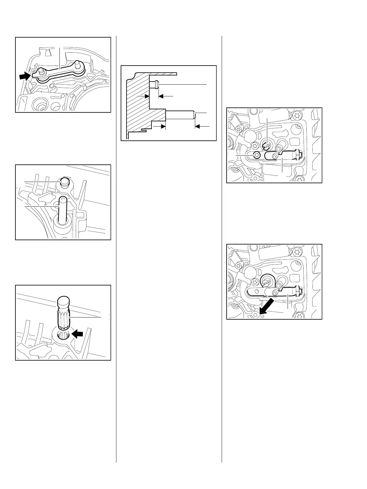
: Position link (1) with the tab
(arrow) facing the edge of the
cover and push it into its seat as
far as stop.
: Use suitable tool to pull the
anchor pin (1) and notched
pin (2) out of the cover.
– Before installing the new pin (1),
coat its knurled shank with
Loctite, b 14
: Position the new pin (1) in the
bore (arrow) so that the knurling
on the pin meshes with the
existing knurling in the bore.
7013RA030 TG
1
7013RA031 TG
2
1
1
7013RA032 TG
Turn pin back and forth as
necessary.
View from air filter side.
: Carefully tap home the anchor
pin (1) and notched pin (2) to
obtain the following dimensions:
Anchor pin (1) a = 4.8 mm
Notched pin (2) b = 25.5 mm
The pins must be driven home
squarely.
– Lubricate the brake lever and flat
spring with STIHL lubricant,
b 14
– Reassemble all other parts in the
reverse sequence.
7013RA033 TG
1
2
a
b
5.6 Chain Tensioner
– Disengage the chain brake and
remove the chain sprocket cover,
bar and chain.
– Troubleshooting, b 3.2
: Turn the spur gear (1) clockwise
until the tensioner slide (2) butts
against the right-hand end.
: Take out the screw (3).
: Pull out the complete chain
tensioner (1).
7013RA034 TG
1
2
3
7013RA035 TG
1
 Loading...