86 MS 201, MS 201 C, MS 201 T, MS 201 TC
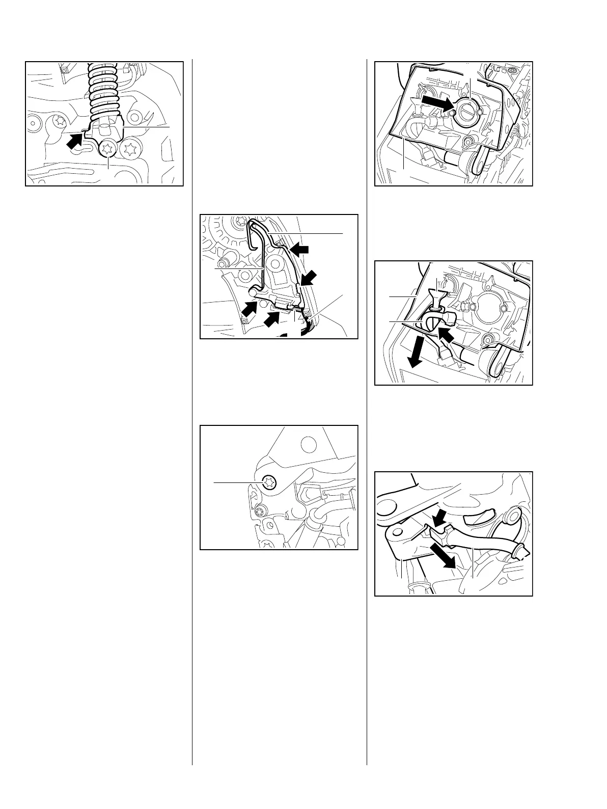
: Push bearing plug (1) with lug
into recess (arrow) in crankcase
as far as stop.
: Coat the screw (2) with Loctite, fit
it and tighten it down firmly, b 14
– Install annular buffer on the fuel
tank, b 9.1
– Install the ignition module, b 7.2
– Fit cover on oil pump and push
bumper strip into its seat, b 9.2
– Install the tank vent, b 12.9.2
– Install the carburetor, b 12.4
– Reassemble all other parts in the
reverse sequence.
10.5 Handle Housing
(MS 201 T)
– Remove cover from oil pump and
pry out the bumper strip, b 9.2
– Remove the AV spring, b 9.2.1
– Remove the carburetor, b 12.5
– Remove the tank vent, b 12.9
7013RA075 TG
1
2
– Remove the choke and throttle
rods with double lever, b 10.3.2
– Remove the lockout lever and
throttle trigger, b 10.3
– Remove the switch shaft,
b 10.1.2
– Remove the handlebar, b 9.3.1
: Pull contact spring (1) of short
circuit wire (2) and contact
spring (3) of ground wire (4) out
of guides (arrows).
: Take out the screw (1).
4
7013RA296 TG
1
2
3
7013RA299 TG
1
: Lift the handle housing (1) a little
and push out the manifold (2) in
direction of cylinder.
: Lift the handle housing (1) a little
and pull the tank vent hose (2)
and fuel suction hose (3) through
the opening (arrow).
: Turn the handle housing (1) over
and pull the impulse tube (2) out
of its seat (arrow) in the handle
housing.
2
7013RA300 TG
1
2
7013RA301 TG
3
1
7013RA302 TG
21
 Loading...