111MS 201, MS 201 C, MS 201 T, MS 201 TC
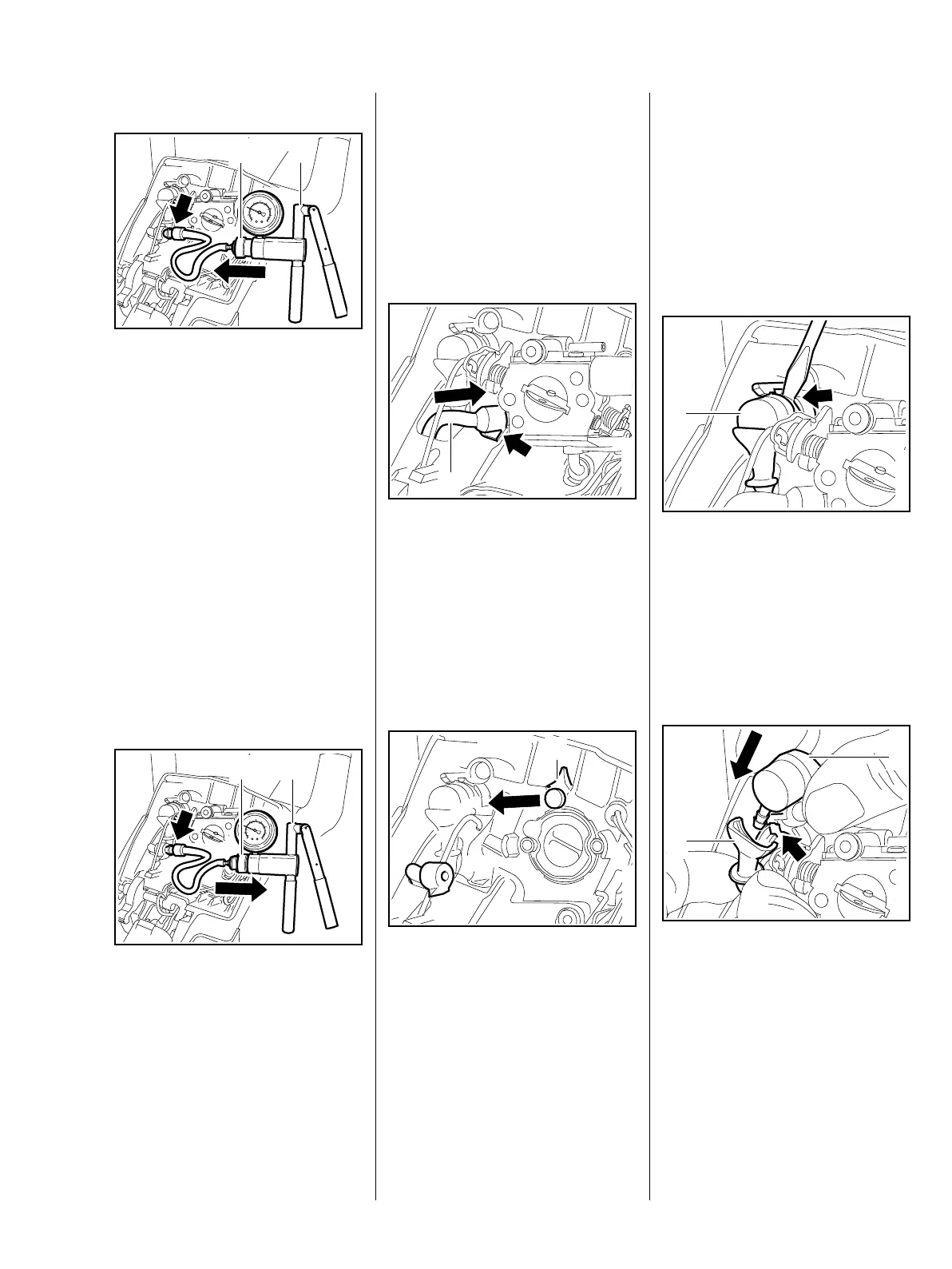
Vacuum test
: Push the ring (1) to the left and
connect the pump (2)
0000 850 1300 to the nipple
(arrow)
– subject the fuel tank to a
vacuum.
Equalization of pressure takes
place via the tank vent. There must
be no buildup of vacuum in the tank.
– Clean the area around the tank
vent.
– Install new tank vent if necessary
MS 201 b 12.9.2,
MS 201 T b 12.9.3
Pressure test
: Push the ring (1) to the right and
connect the pump (2)
0000 850 1300 to the nipple
(arrow)
– pressurize the fuel tank.
2
1
7013RA265 TG
2
1
7013RA266 TG
– Operate the pump until the
pressure gauge indicates a
pressure of 0.5 bar. If this
pressure remains constant for at
least 20 seconds, the tank,
including the tank vent, is airtight.
If the pressure drops, the leak
must be located and the faulty
part replaced.
– Pull the nipple out of the fuel
suction hose.
: Push the fuel suction hose (1)
onto the nipple so that the tab
matches the contour (arrow) of
the handle housing.
Models with manual fuel pump
: Pull plug out of fuel suction
hose (1).
– Install the carburetor,
MS 201 b 12.4,
MS 201 T b 12.5
7013RA267 TG
1
7013RA463 TG
1
All models
– Reassemble all other parts in the
reverse sequence.
12.9.2 Tank Vent (MS 201)
– Remove the filter base, b 12.3
: Use a screwdriver to pry out the
tank vent (1) at the recess
(arrow).
– Pull the tank vent (1) out of the
hose.
Always install a new tank vent.
– Position the new tank vent (1) so
that it points toward the seat.
: Push the tank vent (1) into the
vent hose (2) and into its seat
(arrow) as far as stop.
– Reassemble all other parts in the
reverse sequence.
7013RA268 TG
1
7013RA269 TG
1
2
 Loading...