118 MS 201, MS 201 C, MS 201 T, MS 201 TC
: Fit the fuel hose (1) so that its
groove is properly seated in the
opening (arrow) and its shoulder
(arrow) engages the fuel return
hose (2).
– Install the tank housing, b 12.11
– Install the manifold, b 12.8
– Fit cover on the manifold, b 12.8
– Fit the cover, b 12.8
– Fit the handle housing,
MS 201 b 10.4,
MS 201 T b 10.5
– Install the tank vent,
MS 201 b 12.9.2,
MS 201 T b 12.9.3
– Install the carburetor,
MS 201 b 12.4,
MS 201 T b 12.5
– Reassemble all other parts in the
reverse sequence.
7013RA426 TG
2
1
12.11 Tank Housing
Removing and Installing
If a mounting thread for plastic
tapping screws is damaged, the
tank housing can be repaired by
fitting a thread insert.
– Drain the fuel tank, b 1
– Remove the carburetor,
MS 201 b 12.4,
MS 201 T b 12.5
– Remove the tank vent,
MS 201 b 12.9.2,
MS 201 T b 12.9.3
– Loosen AV elements, remove
handle housing,
MS 201 b 10.4,
MS 201 T b 10.5
– Remove the cover, b 12.8
– Remove the impulse hose,
b 12.8.1
– Remove cover from manifold,
b 12.8
– Remove the manifold, b 12.8
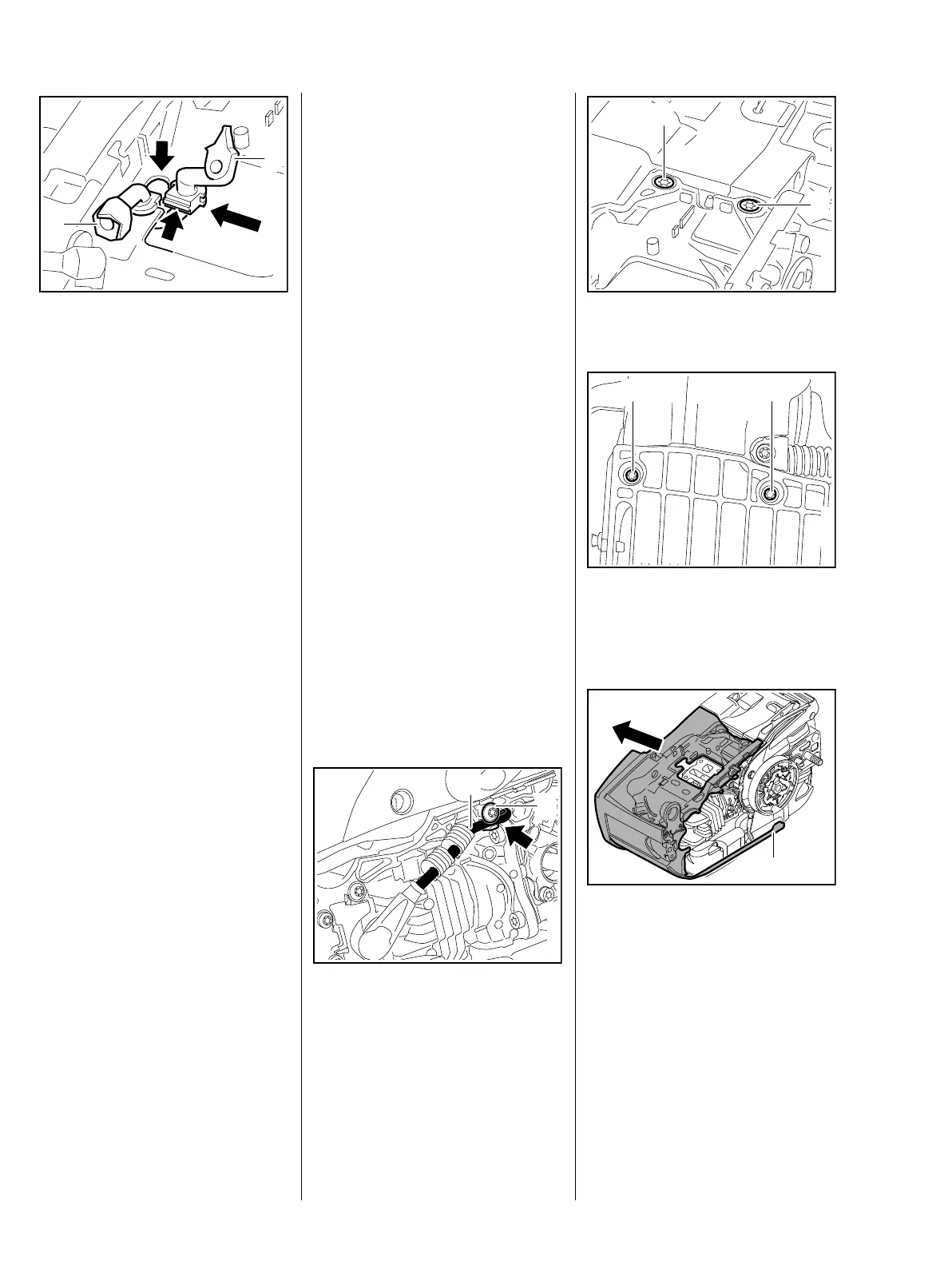
: Take out the screw (1) and pull
the ignition lead (2) out of the
guide (arrow).
7013RA474 TG
2
1
: Take out the screws (1).
– Turn the machine over.
: Take out the screws (1).
: Lift the tank housing (1) a little
and take it out.
– Inspect the tank housing and
replace if necessary.
Only transfer those parts from the
old tank housing that are not
included with the replacement – see
parts list.
7013RA407 TG
1
1
7013RA408 TG
1
1
7013RA409 TG
1
 Loading...