4) If the measured resistance between each terminal
(
@ and
@
1
and the body is “ZERO (0)” ohm, the
ECM is grounded securely at two points. If the resistance is not “ZERO (0)” ohm, the possibility is
that the lead wire between the terminal
(0
or @
)
and the ground is not securely grounded or
disconnected.
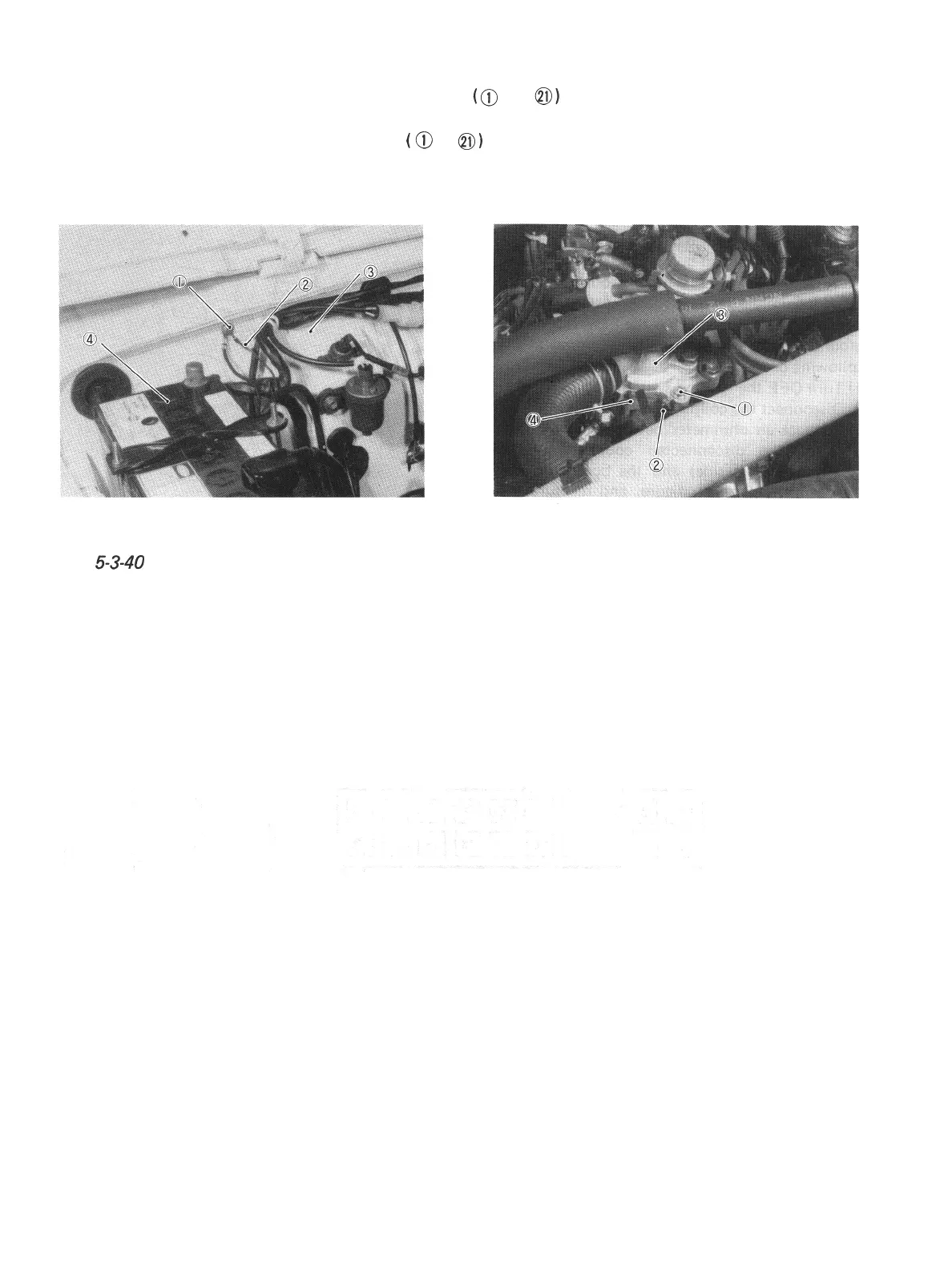
The below figures show the particular points where “B” and “B/G” wires are grounded. Check for
their secure grounding by referring to these figures.
1. Body ground
3. Dash panel
2. Black/Green lead wire 4. Battery
Fig. 5-3-40 Body ground
1. Engine ground 3.
Thermostat
cap
2. Black lead wire
4. Intake manifold
Fig.
5-3-4
1
Engine ground
5) After checking, connect the coupler to ECM securely.
5-30

 Loading...


