Fig. 19-36
Front Brake Disc and Pad
Use care not to scratch or put oil or grease
on sliding surface of disc and pad during
installation work.
After installing brake disc to wheel hub
properly, tighten wheel nuts to specified
torque.
Front Wheel Spindle
Apply SEALING COMPOUND 366E (99000-
31090) to mating surfaces of brake caliper
holder and steering knuckle.
nter side
Dust
Cover/
When fitting dust cover onto brake caliper
holder, apply SEALING COMPOUND 366E
(99000-31090) to mating surfaces of both parts.
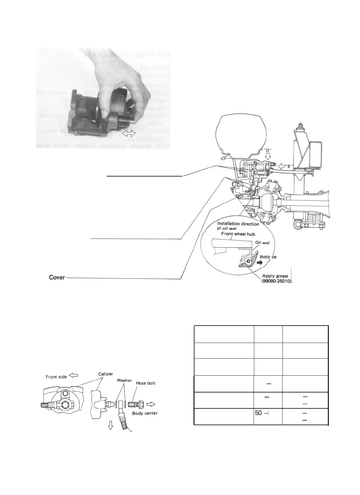
Front Brake Flexible Hose
Connect flexible hose to caliper as shown
below and tighten hose bolt to specified
torque.
Connect the other end of hose to chassis body
bracket, being careful not to kink it with
front wheels directed straightforward.
\
Front side
Flexible hose
Viewed in errow “E”
Viewed in arrow “D” direction
direction
Fig. 19-38
V(gg!&
Fig. 19-37
Tightening torque
Fastening parts N-m
kg-m
(lb-ft)
Flexible hose bolt 20 - 25
2.0 - 2.5
(14.5 - 18.0)
Carrier bolt 70 -100
Caliper holder bolt
40
-
60
Caliper guide pin
25
-
30 2.5
-
3.0
(18.5
-
21.5)
Wheel nut
50-
80
5.0
-
8.0
(36.5
-
57.5)
NOTE:
After completing installation, fill reservoir with
brake fluid and bleed brake system. Perform
brake test and check each installed part for oil
leakage.
(51.0 -72.0)
7.0- 10.0
4.0- 6.0
(29.0 - 43.0)
19-19

 Loading...


