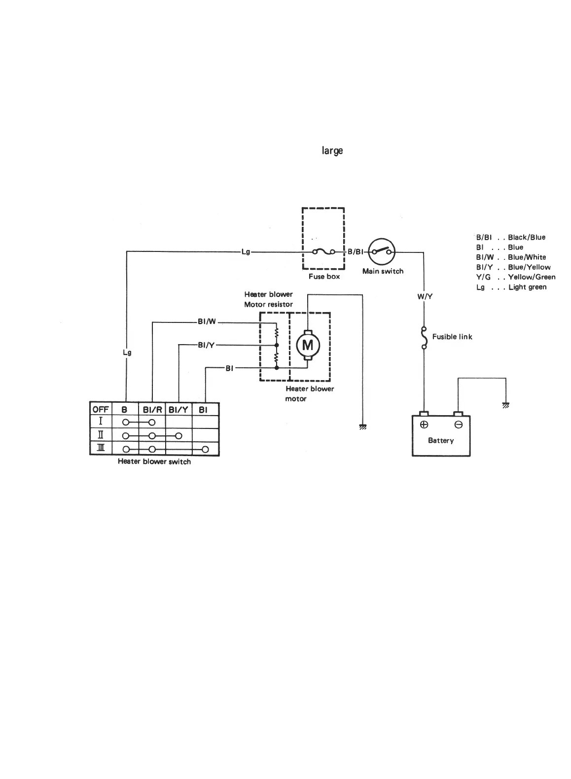
7-2. ELECTRICAL CIRCUIT
The circuit diagram (Fig. 7-2) shows how the blower motor is controlled. Turn the main switch to “ON”,
turn (slide) the blower switch lever on one step, and voltage is applied across the blower motor. The
current is small because of the resistor provided in the circuit (indicated as “blower motor resistance” in
the diagram).
Under this condition, the blower runs slowly. By turning (sliding) the blower switch lever fully,
the
full
battery voltage is applied across the blower motor, a
large
current flows and the blower motor runs at
full speed.
r
-mm-
1
r
i
BlBl . .
Black/Blue
La
BI
. . . Blue
BIIW . .
Blue/White
BUY
. .
Blue/Yellow
Y/G . .
Yellow/Green
Heater blower
La
. . . Light green
Motor resistor
,
,
w~
motor
Heater blower switch
Fusible link
I
Fig. 7- 2
7-3

 Loading...


