MASTER CYLINDER ASSEMBLY
[GENERAL DESCRIPTION]
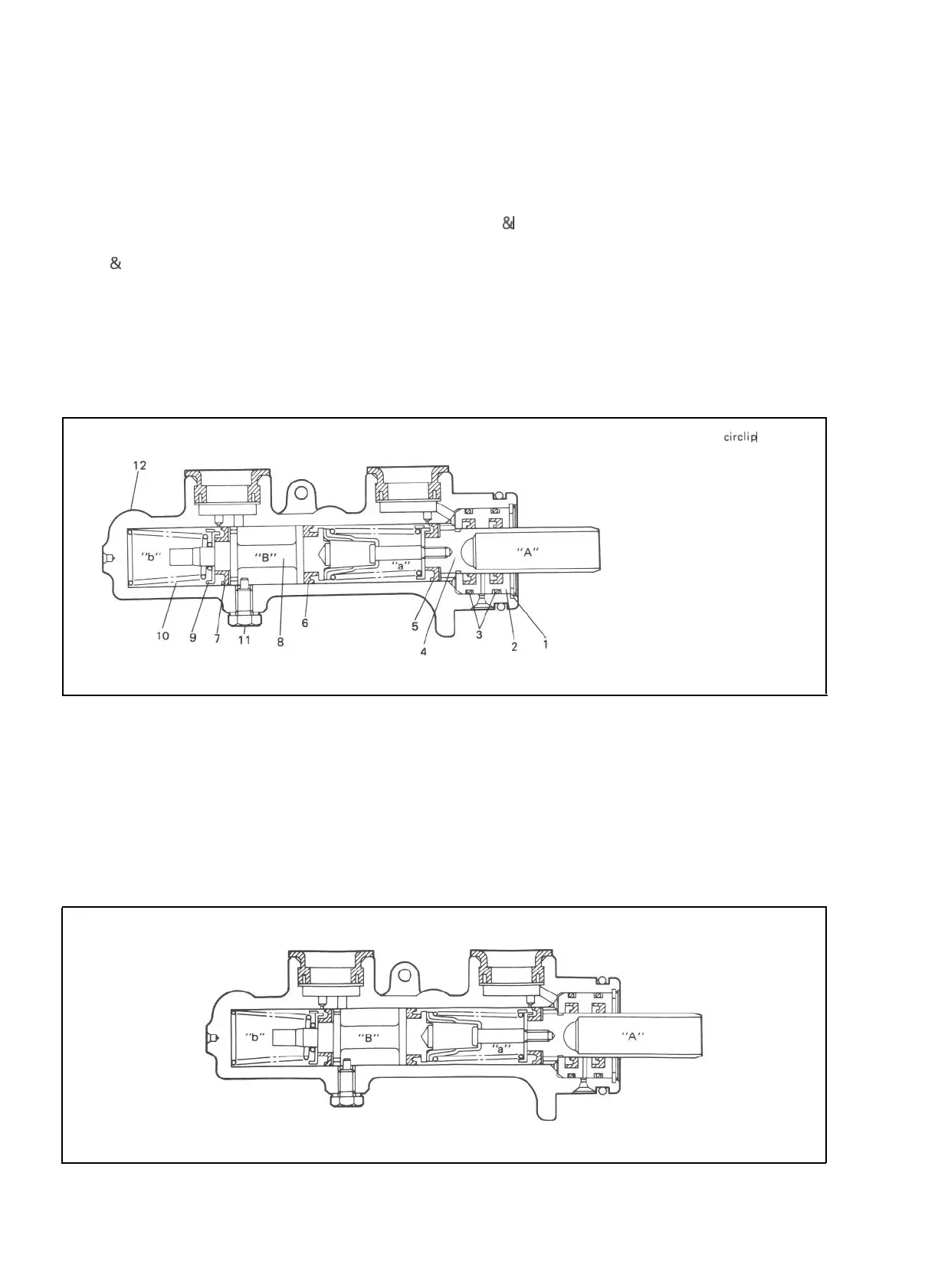
The master cylinder has two pistons and three piston cups. Its hydraulic pressure is produced in the
primary (“a” in the below figure) and secondary (“b”) chambers. The hydraulic pressure produced in the
primary chamber (“a”) acts on the front wheel brakes (right
&
left).
Also, the hydraulic pressure produced in the secondary chamber (“b”) acts on the rear wheel brakes
(right & left).
NOTE:
Replace all components included in repair kits to service this master cylinder. Lubricate rubber parts with
clean, fresh brake fluid to ease assembly. Do not use lubricated shop air on brake parts as damage to rubber
components may result. If any hydraulic component is removed or brake line disconnected, bleed the
brake system. The torque values specified are for dry, unlubricated fasteners.
1.
Piston stopper circllp
2.
Piston stopper
3.
Piston stopper sealing
4.
Primary piston
5.
Piston cup
6.
Secondary piston pressure cup
7.
Piston cup
8
Secondary piston
9.
Return spring secondary seat
10.
Secondary piston return spring
11. Secondary piston stopper bolt
12. Master cylinder body
A :
Primary piston
B Secondary piston
Fig. 19-3
[Master cylinder OPERATION]
Normal operation
Depressing the brake pedal forces the primary piston
“A” to move to the left in the below figure and
consequently the hydraulic pressure is produced in the chamber “a”.
By means of this pressure and the return spring force, the secondary piston “B” is also pushed to the left
and thus the hydraulic pressure is produced in the chamber “b”.
Fig. 19-3-1
19-4

 Loading...


