cl
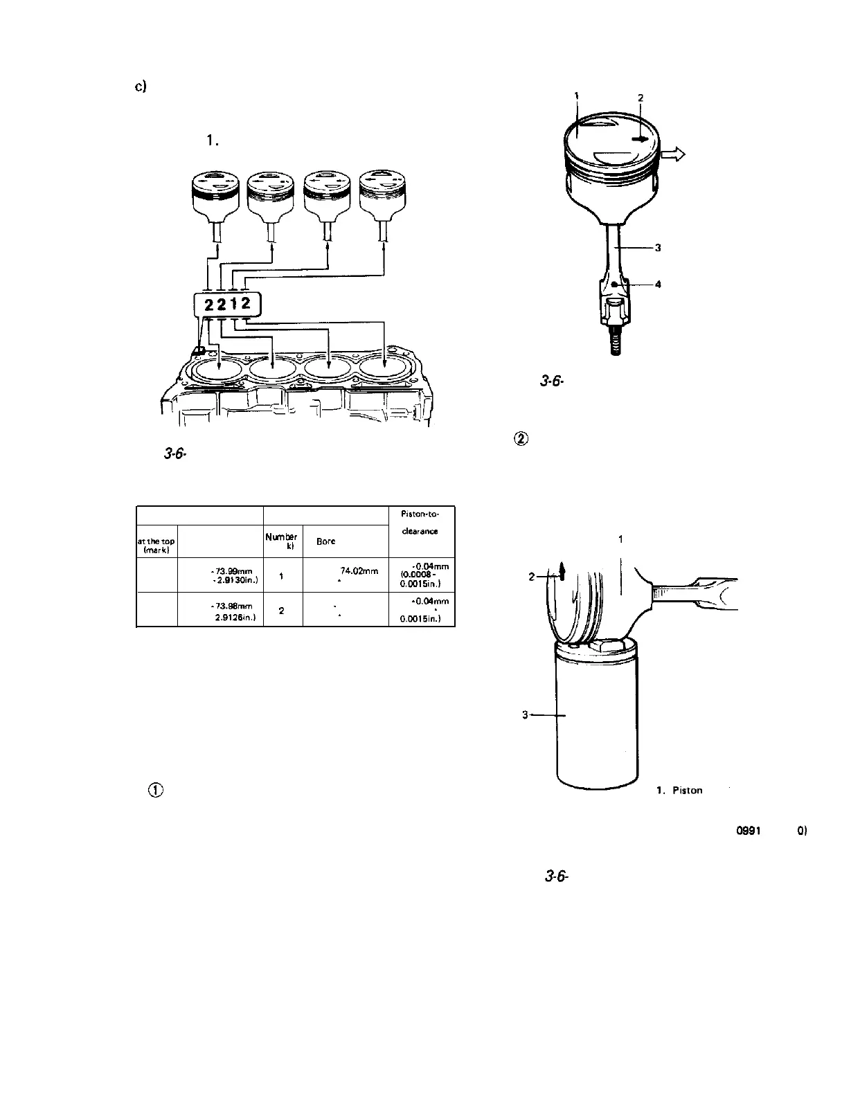
Use a number 2 stamped piston for installa-
tion if cylinder is identified with number 2
and a number 1 piston for cylinder with
number
1.
Fig.
3-6-
11
Piston
Cylinder
Piston-to-
cylinder
Number
a;$;r$p
Outside diameter
NWtlber
ck?arancE
(mar
kb
Bore
diameter
1
73.96
-
73.99mm
’
74.01 74.02mm
0.02
-
0.04mm
(2.9126
-
2.9130in.)
(2.9138
-
2.9142in.l
~0.0009
-
0.0016in.)
2
73.97
-
73.96mm
74.00
-
74.01 mm
0.02
-
0.04mm
2
(2.9134
-
2.9138in.l
(0.0008
-
0.0016in.l
Also, a letter A, 6, C etc., is stamped on piston
head but ordinarily it is not necessary to dis-
criminate each piston by this number.
1) Install connecting rod to piston.
@
After applying engine oil to piston pin holes
in piston and connecting rod, fit connecting
rod to piston as prescribed in Fig. 3-6-12.
Crankshaft pulley side
1. Piston
2. Arrow mark
3. Connecting rod
4. Oil hole
(Oil hole should come on
intake side)
Fig.
3-6-
12 Fitting connecting rod to piston
@
Place piston on piston pin remover and
installer (special tool) as indicated in Fig.
3-6-13, and press piston pin into piston and
connecting rod (Fig. 3-6-14).
2. Arrow mark
3. Piston pin remover and installer
(Special tool 0991 O-3821 0)
Fig.
3-6-
13 Fitting piston to special tool
3-39
(2.9122-

 Loading...


