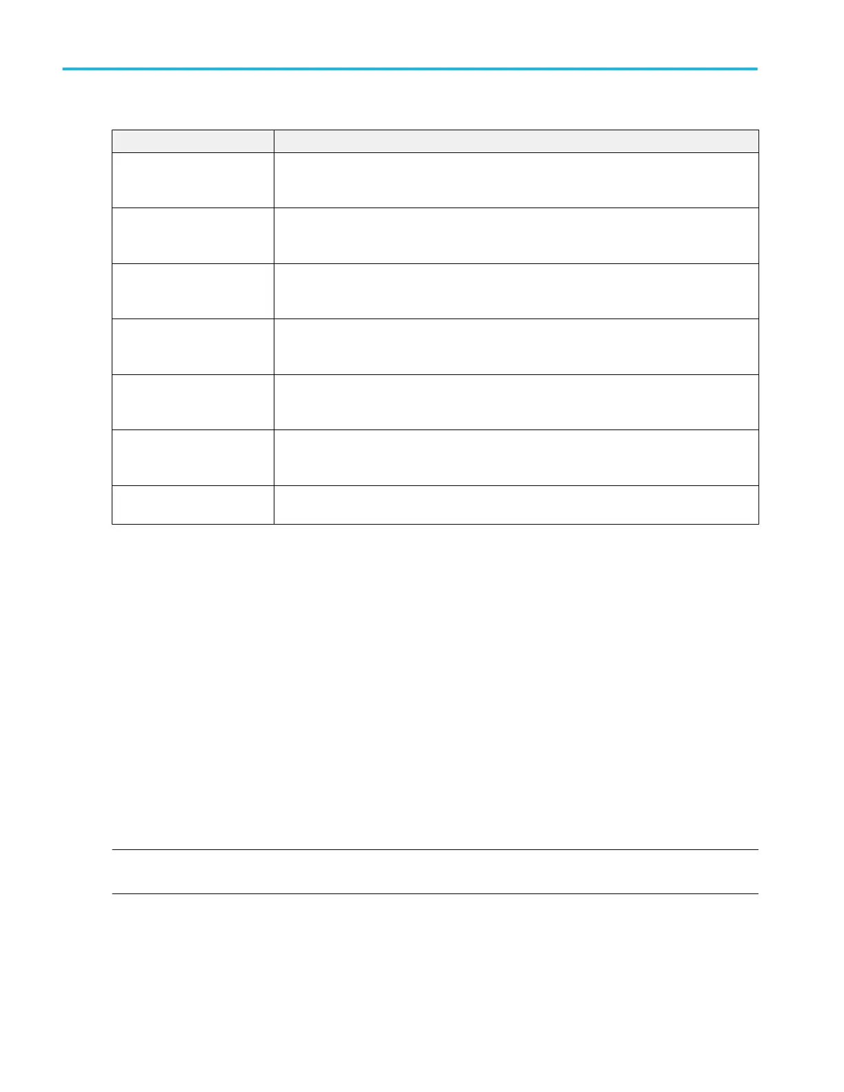
Measurement Description
Positive Pulse Width
2
The distance (time) between the mid reference (default 50%) amplitude points of a positive
pulse.
The measurement is made on the first pulse in the measurement region.
Rise Time The time required for the leading edge of the first pulse in the measurement region to rise from
the low reference value (default = 10%) to the high reference value (default = 90%).
The measurement is taken on each cycle of the waveform record.
Rising Slew Rate The rate of change (in volts/second) as an edge transitions from a low reference level to a high
reference level.
The measurement is taken on each cycle of the record in the measurement region.
Setup Time
2
The time between the specified Mid reference level crossing on the data signal to the closest
Mid reference level crossing on the specified clock signal.
The measurement is made on each specified clock edge in the waveform record.
Skew
2
The time between the specified Mid reference level crossing on one source to the closest Mid
reference level crossing on the second source signal.
The measurement is made on each cycle in the waveform record.
Time Outside Level The time the specified signal remains above the Top reference level and/or below the Base
reference level.
The measurement is made on each occurrence in the waveform record.
Unit Interval
2
The time difference between two successive bits.
The measurement is taken on each bit of the waveform record.
See also. Measurement configuration menu overview on page 164
Jitter Measurements panel
The Jitter Measurements panel lists the standard jitter-related measurements that you can add to the Results bar. These jitter
measurements are part of the Standard measurements that are provided by default.
To open the Jitter Measurements panel:
1. Tap the Add New...Measure button.
2. Tap the Jitter Measurements panel.
To add a measurement to the Results bar:
1. Select the signal source.
2. Select a measurement.
3. Tap Add. You can also double-tap a measurement to add it immediately to the Results bar.
NOTE. If you have installed Advanced Jitter and Eye Analysis option, the jitter measurements are moved to the Jitter tab of the
Add Measurements menu. See The Jitter tab (Advanced Jitter and Eye Analysis) (optional) on page 157.
Menus and dialog boxes
156 MSO54, MSO56, MSO58, MSO58LP, MSO64 Help
 Loading...


