See also. Power measurement configuration menu overview
Measurement configuration menu overview
Use this configuration menu to add statistics to a measurement badge readout, plot a measurement, and change measurement
settings including source, scope (global or local), reference levels, gating, clock recovery, bandwidth filters, and results limits.
To open a Measurement configuration menu for a measurement, double-tap a Measurement badge in the Results bar. The
configuration menu and panels only show fields and controls relevant to the selected measurement.
The menu opens on the measurement name panel (the name of the measurement), which provides controls to display additional
statistics to the measurement badge, display plots of the measurement, and so on. The content of the measurement name panel
depends on the measurement. The most common Measurement Name fields are listed in the following table.
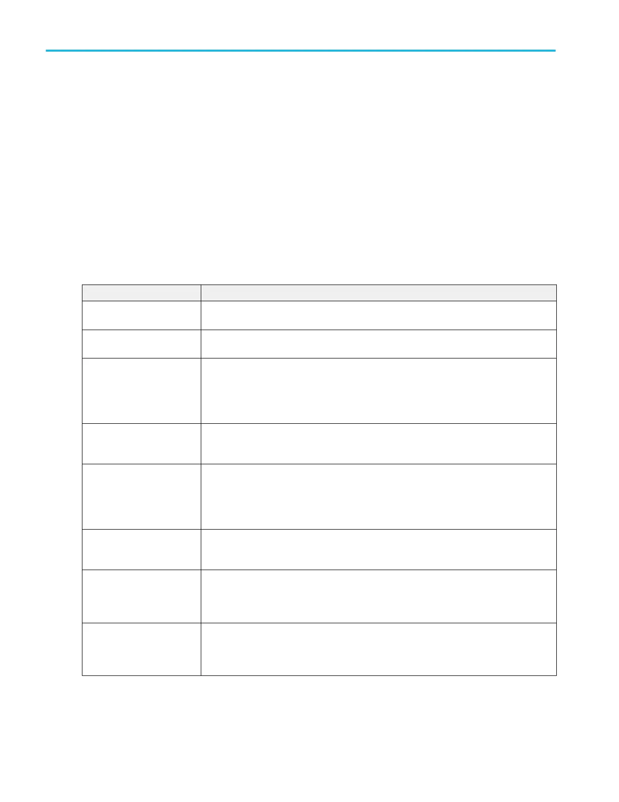
Measurement configuration menu fields, controls, and panels
Field, control, or panel Description
Measurement Statistics
(Measurement name panel)
A list of measurement statistics related to the measurement. You can add these statistics to a
measurement badge by selecting the Show Statistics in Badge control.
Show Statistics in Badge
(Measurement name panel)
Adds the listed statistical measurement readouts to the measurement badge readout.
Plots
(Measurement name panel)
Buttons that open Plot views of the measurement. Available plots depend on the measurement.
Plot types include Time Trend, Histogram, Spectrum, and Eye Diagram (for jitter
measurements). To add a plot to the screen, tap the plot button.
See Add Plot configuration menu on page 219.
Configure panel Sets the source, label text, and other fields that are specific to each measurement type.
See Configure panel (Measurement configuration menu) on page 165.
Reference Levels panel Sets the reference levels and units used to take measurements, the scope of the reference
level settings (global or local), and the method used to calculate the Top and Base waveform
values.
See Reference Levels panel (Measurement configuration menu) on page 166.
Clock Recovery panel
(jitter measurements)
Sets the clock recovery settings for some jitter measurements.
See Clock Recovery panel (Measurement configuration menu) on page 168.
Gating panel Sets the measurement region (gate) used to take measurements. Select the scope of the gate
setting (global or local), and the type of gating to use.
See Gating panel (Measurement configuration menu) on page 173.
Filter/Limit Results panel Sets the scope of the filtering setting (global or local), high and low pass filter settings, the
range of measurement result limits, and the limit measurement population size.
See Filter/Limit Results panel (Measurement Settings menu) on page 174.
Menus and dialog boxes
164 MSO54, MSO56, MSO58, MSO58LP, MSO64 Help
 Loading...


