Pulse width trigger concepts
A pulse width trigger occurs when the instrument detects a pulse that is inside or outside some specified time range. The
instrument can trigger on positive or negative width pulses. Pulse width triggers can also be qualified by the logical state of other
channels.
Timeout trigger
A timeout trigger occurs when the instrument does not detect an expected pulse transition within a user specified period of time,
such as when a signal gets stuck either high or low. If the pulse transition occurs prior to a specified timeout time (the expected
case), then no trigger results.
Runt trigger
A runt trigger occurs when the instrument detects a short pulse that crosses one threshold but fails to cross a second threshold
before recrossing the first.
■
You can set the instrument to detect any positive or negative runt pulse, or only those wider than a specified minimum width.
■
Runt pulses can also be qualified by the logical state of other channels.
Window trigger
Use the Window trigger to trigger the instrument when the input signal rises above an upper threshold level or falls below a lower
threshold level.
After setting these levels, you can specify whether you want to trigger the instrument as the signal is entering or leaving the
threshold window. You can further qualify the trigger event in terms of time, or by the logical state of other channels.
Logic trigger concepts
For various trigger types, touch Logic Qualification to toggle logic qualification On to trigger the instrument when the logic
patterns are true. You can set each bit to be active High, Low, or Don't Care. You can also set the logic thresholds and define the
logic (AND, OR, NOR, or NAND).
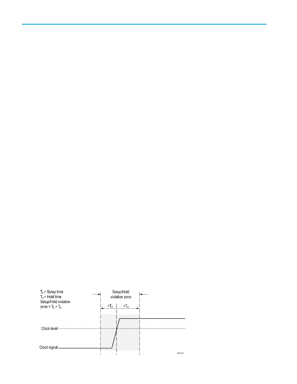
Setup and Hold trigger concepts
A setup/hold trigger occurs when a data signal changes state inside of the user specified setup and hold times relative to the
clock. When you use setup/hold triggering, you define:
■
The channel containing the logic input (the data source) and the channel containing the clock (the clock source)
■
The direction of the clock edge to use
■
The clocking level and data threshold that the instrument uses to determine if a clock or data transition has occurred
■
The setup and hold times that together define a time range relative to the clock
Data that changes state within the setup/hold violation zone triggers the instrument. The next figure shows how the setup and
hold times that you choose position the violation zone relative to the clock.
Trigger concepts
424 MSO54, MSO56, MSO58, MSO58LP, MSO64 Help
 Loading...


