Balancer
Inspection
1.
Inspect all gears for chipped or missing teeth
and
for
overheating (blue discolouration).
2.
Inspect
all
bearings for signs
of
overheating (blue
discolouration), seizure
and
any other damage.
Check that all bearings rotate smoothly
and
without tight spots.
Note:
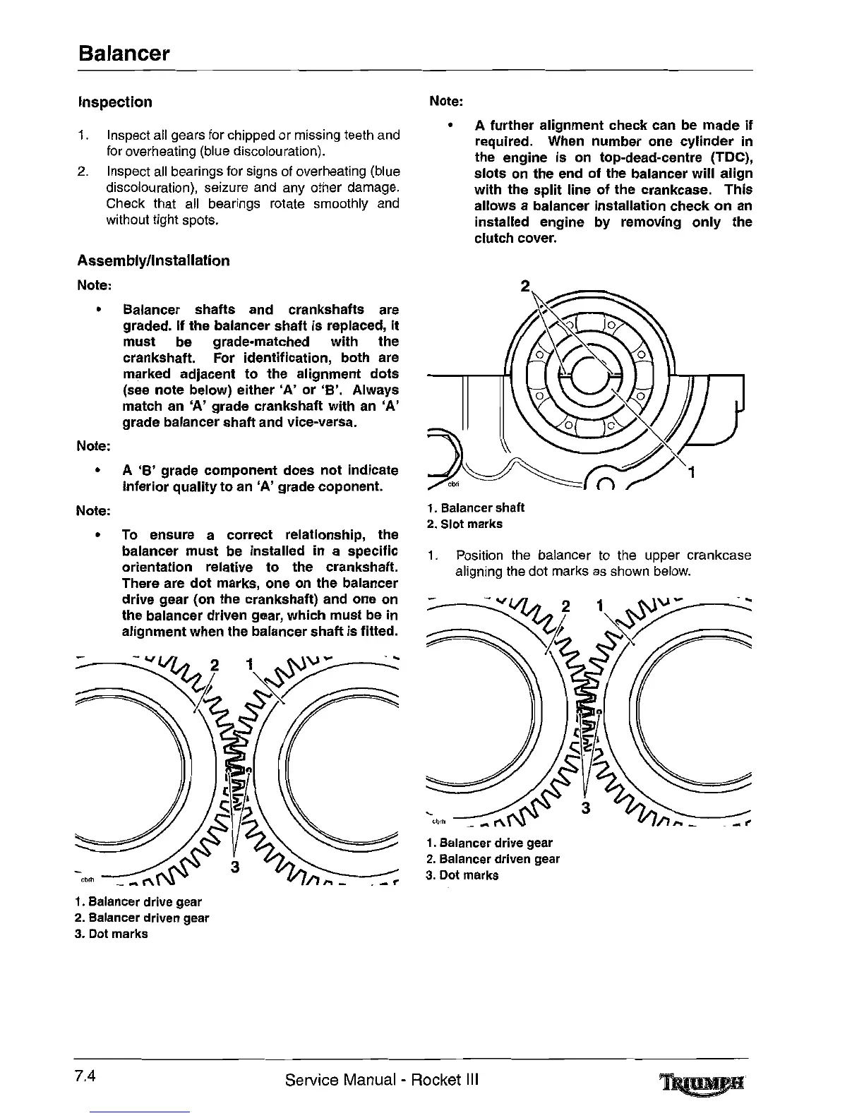
• A further alignment check can be
made
if
required. When number one
cylinder
in
the engine is on top-dead-centre (TOe),
slots
on
the
end
of
the
balancer
will
align
with the
split
line
of
the crankcase.
This
allows a balancer installation check
on
an
installed engine by removing
only
the
clutch cover.
Assembly/lnstallation
Note:
• Balancer shafts and crankshafts are
graded.
If the balancer shaft is replaced,
it
must be grade-matched with
the
crankshaft. For identification, both are
marked adjacent
to
the
alignment
dots
(see note below) either
'A'
or
'B'.
Always
match an
'A'
grade crankshaft with an
'A'
grade balancer shaft and vice-versa.
Note:
•
A
'B'
grade component does
not
indicate
inferior quality
to
an
'A'
grade coponent.
cbrh
1. Position the balancer to the upper crankcase
aligning the dot marks
as
shown
below.
1.
Balancer shaft
2.
Slot
marks
1.
Balancer drive
gear
2.
Balancer driven
gear
3.
Dot
marks
Note:
• To ensure a correct relationship, the
balancer
must
be installed in a specific
orientation relative
to
the crankshaft.
There are
dot
marks, one on the balancer
drive gear (on the crankshaft) and one on
the
balancer driven gear, which must be in
alignment when the balancer shaft is fitted.
1.
Balancer drive gear
2.
Balancer driven
gear
3.
Dot
marks
7.4
Service Manual - Rocket
III
 Loading...