Crankshaft
Piston Rings/Ring Grooves
1. Check the pistons for uneven groove wear by
visually inspecting the ring grooves.
2.
Clean the piston ring grooves.
3. Fit the piston rings to the pistons. Check, using
feeler gauges, for the correct clearance between
the ring grooves and the rings. Replace the
piston and rings if outside the specified limit.
Checking piston ring to groove clearances
Piston ring/Groove Clearance
Top - standard
0.02 -
0.06
mm
Top - service limit
0.16 mm
Second - standard
0.02 -
0.06
mm
Second - service limit
0.16 mm
Piston Ring Gap
Note:
• Before final assembly the piston ring gap,
when fitted
in
the liner, must first be
checked.
1. Place the piston ring inside the liner.
2. Push the ring into the top of the cylinder, using
the piston to hold the ring square with the inside
of the bore. Continue to push the ring into the
bore until the third groove of the piston
is
level
with the top of the liner around its full
circumference.
",,,
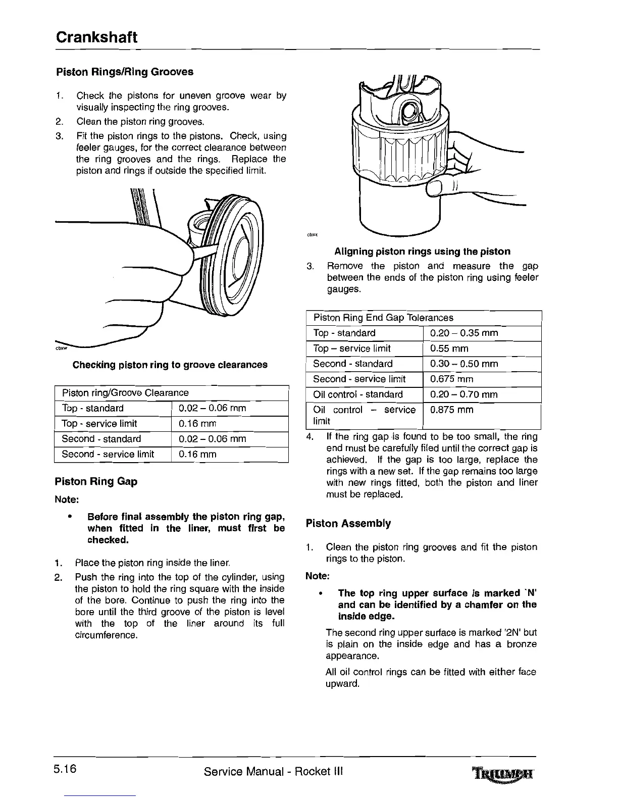
Aligning piston rings using the piston
3.
Remove the piston and measure
the
gap
between the ends of the piston ring using feeler
gauges.
Piston Ring End Gap Tolerances
Top
- standard
0.20 - 0.35 mm
Top
- service limit 0.55 mm
Second - standard
0.30 -
0.50
mm
Second - service limit
0.675 mm
Oil control - standard
0.20 - 0.70 mm
Oil control
- service 0.875 mm
limit
4.
If
the nng gap
IS
found to be too small, the nng
end must be carefully filed until the correct gap
is
aChieved. If the gap is too large, replace the
rings with a new set. If the gap remains
too
large
with new rings fitled, both the piston and liner
must be replaced.
Piston Assembly
1.
Clean the piston ring grooves and fit
the
piston
rings to the piston.
Note:
•
The
top ring upper surface is marked .N'
and
can
be identified
by
a chamfer
on
the
inside edge.
The second ring upper surface is marked '2N' but
is
plain on the inside edge and has a bronze
appearance.
All oil control rings can be fitted with either face
upward.
5.16
Service Manual - Rocket
III
 Loading...