Crankshaft
Crankcases
The following procedures often require lifting
of
heavy components.
To
avoid
injury, always lift heavy
components
with
a hoist or block and tackle
and
never attempt
to
manually lift items that are too
heavy.
Injury
may
result from failure to
use
the
correct lifting equipment.
The upper
and
lower crankcases are machined
as
a
matched
set
and
must never
be
assembled to non-
matching halves. Doing
so
will cause seizure of the
engine.
Note:
• The crankcase halves may be separated
with
the
cylinder head fitted.
Removal
1.
Remove
the
engine from the frame (see page
10.2).
2.
Remove
the
clutch
(see
page
4.7).
3.
Remove the starter motor
(see
page
18.18)
.
4.
Remove
the
alternator (see page 18.15).
5.
Remove the oil pump drive and pressure
oil
pump (see page 9.11).
6.
Remove the torsional damper shaft (see page
8.11).
7.
Remove the sump (see
page
9.9).
8.
Remove
the
cam
chain (see page 3.6).
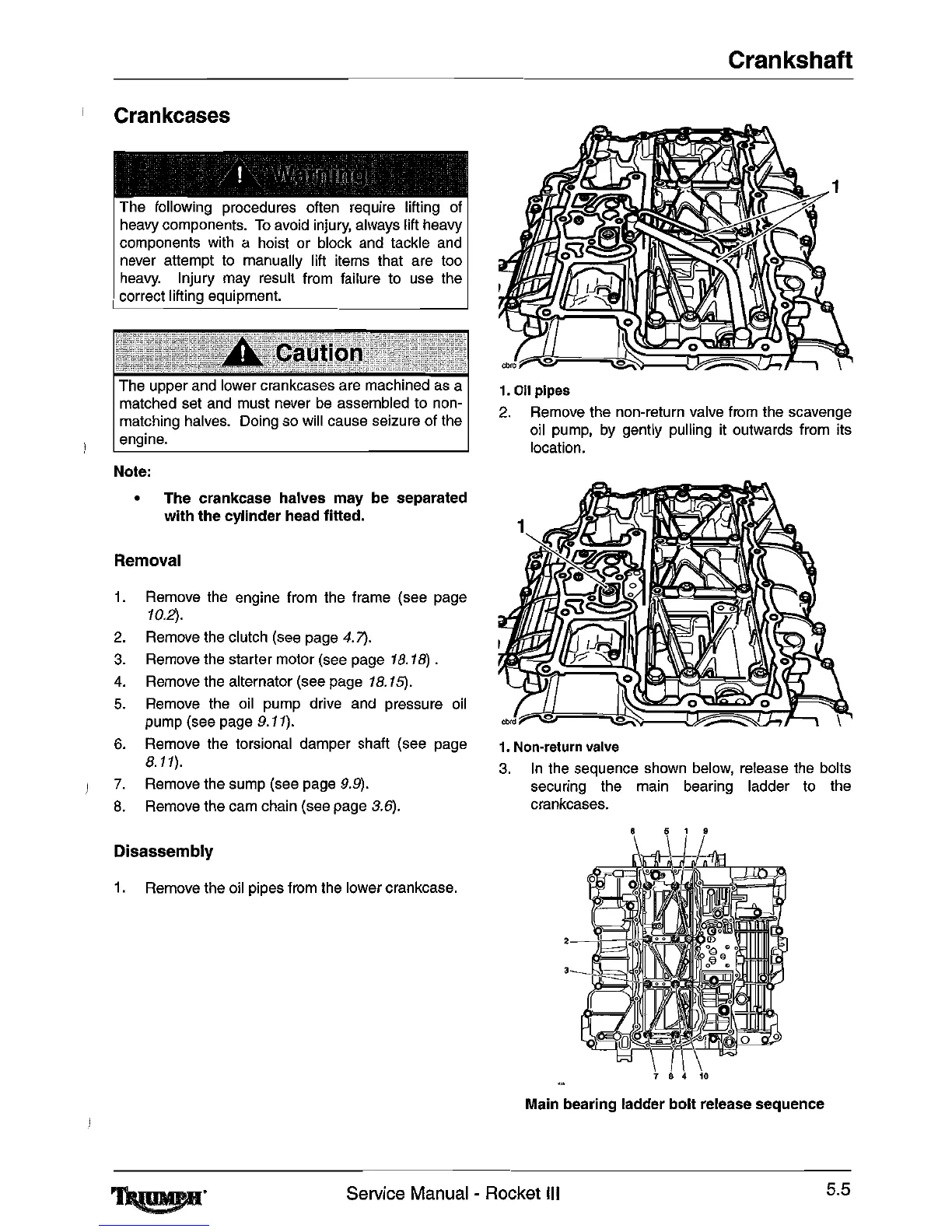
1.011
pipes
2.
Remove the non-return valve from the scavenge
oil
pump,
by
gently
pUlling
it
outwards from its
location.
1.
Non-return
valve
3.
In
the
sequence
shown
below,
release
the
bolts
securing the main bearing ladder
to
the
crankcases.
6 5 1 9
Disassembly
1.
Remove the oil pipes from
the
lower crankcase.
2
Main bearing ladder
bolt
release sequence
~.
Service Manual - Rocket III
5.5

 Loading...