Cylinder Head
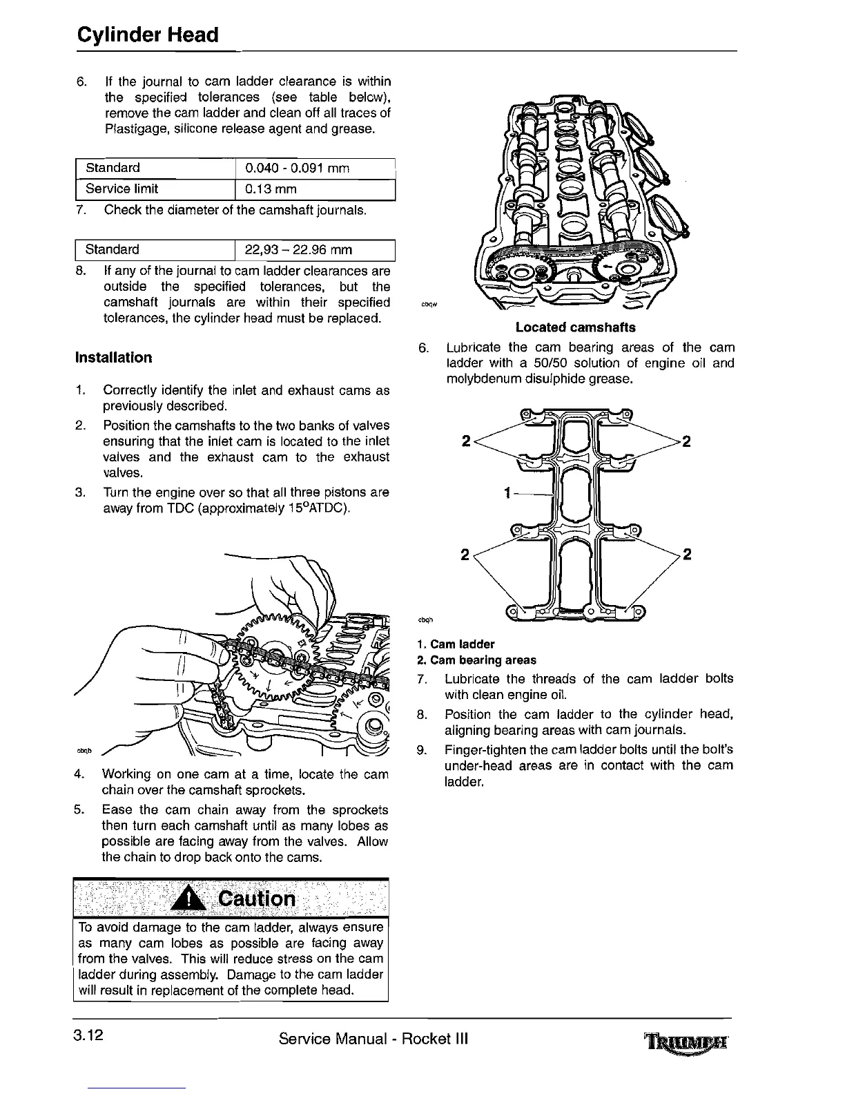
Located camshafts
6.
Lubricate the cam bearing areas of the cam
ladder with a
50/50 solution of engine oil
and
molybdenum disulphide grease.
""h
1.
Cam ladder
2.
Cam bearing areas
7.
Lubricate the threads of the cam ladder bolts
with clean engine
oil.
8.
Position the cam ladder
to
the cylinder head,
aligning bearing areas with
cam
journals.
9.
Finger-tighten the cam ladder bolts until the bolt's
under-head areas are
in
contact with the cam
ladder.
0.040 - 0.091
mm
0.13
mm
Standard
Service limit
7.
Check the diameter of the camshaft
Journals.
Installation
6.
If
the
journal
to
cam ladder clearance
is
within
the specified tolerances (see table below),
remove the
cam
ladder and clean off
all
traces
of
Plastigage, silicone release agent
and
grease.
1.
Correctly identify the inlet
and
exhaust cams
as
previously described.
2.
Position the camshafts
to
the
two
banks
of
valves
ensuring that the inlet cam
is
located
to
the inlet
valves and the exhaust cam
to
the exhaust
valves.
3.
Turn
the engine over
so
that
all
three pistons are
away from TDC (approximately 15°ATDC).
4.
Working
on
one cam at a time, locate the cam
chain over the camshaft sprockets.
5.
Ease the cam chain away from the sprockets
then turn each camshaft until
as
many lobes
as
possible are facing away from the valves. Allow
the chain
to
drop back onto the cams.
IStandard I22,93 - 22.96
mm
I
8.
If
any of the journal
to
cam
ladder clearances are
outside the specified tolerances,
but
the
camshaft journals are within their specified
tolerances, the cylinder head must
be
replaced.
To
avoid damage to the cam ladder, always ensure
as many cam lobes as possible are facing away
from the valves. This will reduce stress
on
the
cam
ladder during assembly. Damage
to
the
cam
ladder
will result in replacement of the complete
head.
3.12
Service Manual - Rocket
III

 Loading...