Corrective Maintenance
Print Mechanism
162
14207L-001 A ZM400/ZM600 Maintenance Manual 8/9/07
3. Slide the cutter assembly to the left then lift up and remove the assembly from the platen
assembly hooks.
Remove the Print Mechanism
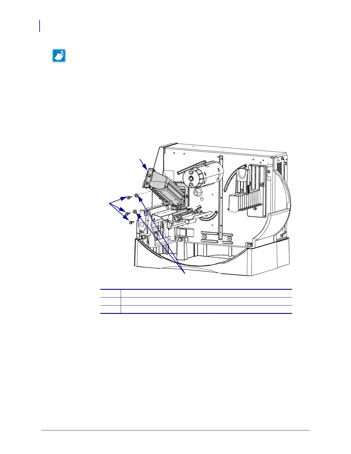
1. See Figure 41.Remove the three mounting screws and two washers.
Figure 41 • Printhead Housing Mounting Screws
2. Remove the printhead housing assembly from the printer. Guide the print mechanism
cable out through the access hole after removing the print mechanism.
Install the New Print Mechanism
1. See Figure 41. Feed the new cables through the print mechanism mounting hole.
2. Install the three print mechanism mounting screws and two washers.
3. Close and latch the print mechanism.
4. See Figure 39 on page 160. Route the printhead power cable under the stepper motor and
up to the power supply.
Note • The cutter guard does not need to be removed from the cutter assembly during this
procedure.
1
Print mechanism
2
Washers (2)
3
Screws (3)
1
2
3
 Loading...