Corrective Maintenance
Printhead Latch
196
14207L-001 A ZM400/ZM600 Maintenance Manual 8/9/07
5. See Figure 67 on page 194. Tighten the adjustment screw until the top of the strike plate is
just below the top of the print mechanism.
6. Install the top mounting screw and washer through the strike plate and into the print
mechanism. Do not tighten at this time; leave them approximately ½ turn loose. Latch the
print mechanism.
7. Insert the stabilizer into the print mechanism until it stops.
8. Install the lower strike plate mounting screw.
Adjust the Print Mechanism
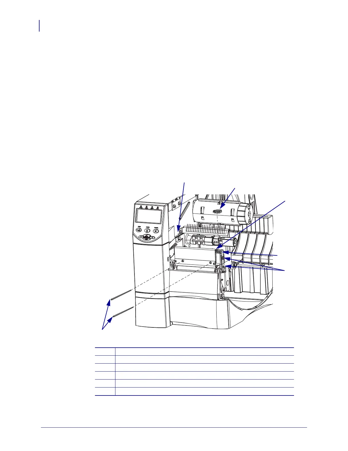
1. See Figure 69. Insert the print mechanism gap pin gauges through the holes that are
provided in the front of the ribbon guide plate.
Figure 69 • Adjust the Print Mechanism
2. Turn the adjustment screw until a small amount of friction is felt on the gap pin gauge.
1
Print mechanism adjustment cam location
2
Strike plate cap
3
Adjustment screw
4
Strike plate
5
Strike plate mounting screws (2)
6
Print mechanism gap pin gauges (2)
1
2
3
4
5
6
 Loading...