ABB | SACE Emax 2
Electronic accessories | 3 - Ekip Measuring modules179 | © 2017 ABB | 1SDH001330R0002 - ECN000058721 Rev. A
Connections
The modules must be mounted on the terminal box of the circuit-breaker or of the fixed part of the withdrawable
circuit-breaker, in the first free slot.
Information on the assembly is available on the website http://www.abb.com/abblibrary/DownloadCenter/, in
particular in the kit sheet 1SDH001000r0511.
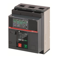
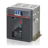
An example with an E2.2 circuit-breaker in fixed and withdrawable versions is provided to the side.
The following is a view of the terminal box of E1.2 and E2.2-E4.2-E6.2 circuit-breakers with the relevant wiring
diagram:
R2
R1
U2
U1
38
36
35
98
96
95
YRMS33S51
YO
EKIP SupplyTrip Unit I/O
Ge-
Ge
Szc
K2
K1
W4
W3
Q4Q3Q2Q1YC
YU
YO2
RTC
I/O
TU
44
42
41
34
32
31
24
22
21
14
12
11
C12
C13
C11
C2
C3
C1
D2
D1
48
46
45
Ne
Rca
Ne-
Gzi
Szo
Szi
Gzo
Rct
Vn
V1
V2
V3
Module Module
YO
01
H4
02
K5
04
K10K9
94
92
H3
9181
H2
82
K4
K8
8474
K7
K3
H1
72
7161
HC
62
64
54
52
51
Trip Unit I/O
HC
K6
Ge-
Ge
Szc
K2
K1
W4
W3
R2
R1
Q4Q3Q2Q1YC2YC
YU
YO2
RTC
I/O
TU
44
42
41
34
32
31
24
22
21
14
12
11
C22
C21
C12
C13
C11
C2
C3
C1
D2
D1
48
46
45
Ne
Rca
Ne-
Gzi
Szo
Szi
Gzo
Rct
Vn
V1
V2
V3
U2
U1
38
36
35
98
96
95
YRMS33S51
EKIP Signalling 4KQ5..Q10
Module Module Module
EKIP Supply
HC
Uaux.
A3
110-240VAC/DC
A4
+/L
-/N
24-48VDC
Ekip Supply 24-48VDC
Ekip Supply 110-240VAC/DC
SUPPLY
K51
A)
**
I)
EKIP
32
K51
A1
XV
X
K1
K1
K1
K2
K2
K2
W3
W3
W3
W4
W4
W4
K1 K2
(B)(A)
(LOCAL BUS)
Q)
*
W2
W3 W4
Diagram 32
For external wiring, AWG 22-16 cables with a maximum external diameter of 1.4 mm must be used.
Further information is available on page 174, or on the website http://www.abb.com/abblibrary/
DownloadCenter/, where the wiring diagram is available 1SDm000091r0001.
Signallings
The following table shows the possible signals, and their meaning:
Pos. Description
A
Power LED, green. The possible states are:
• Off: power supply absent.
• On fixed: power supply present.
3 - Ekip Measuring modules
Description
The Ekip Measuring is an accessory module for measurement of voltage, power and energy.
Specifically:
• It measures the r.m.s. value and frequency of the voltages of the three-phase system on the internal
contacts of the circuit-breaker, or on the external sockets. From these measurements, the trip unit obtains
the power and energy ones, which therefore become available.
• Combined with the Ekip Synchrocheck module, Ekip Measuring makes it possible to recognise whether
the synchronism conditions exist between the internal contacts (or external sockets) and external contacts
necessary for closing the circuit-breaker.
Two types are available:
• Ekip Measuring, equipped with the measuring function only.
• Ekip Measuring Pro, with a measuring function, possibility of powering the trip unit, and activation of the
Measuring protections.
With the Ekip Measuring Pro module, the power supply of the trip unit is guaranteed, if at least one value of
the line-to-line voltages is greater than or equal to 80 V AC.
Compatibility and power supply
The Ekip Touch trip unit can be equipped with the Ekip Measuring and the Ekip Measuring Pro modules, the
former if you only wish to implement the measurement function and the latter if you also wish to implement
the power supply function and activate the Measuring protections. With Ekip Hi-Touch, G Touch, and G Hi-
Touch trip units, Ekip Measuring Pro is provided as standard.
Ekip Measuring requires the trip unit to be also supplied with auxiliary voltage (example: provided by an Ekip
Supply module). Auxiliary supply is not necessary with Ekip Measuring Pro.
Electrical characteristics
The following table lists the electrical characteristics of the modules:
Component Characteristics
Phase-to-phase input voltage 0…760 V AC
Input frequency 30…80 Hz
Isolation transformer
If the input phase-to-phase voltage supplied to the modules is greater than 690 V AC rated voltage (maximum
760 V AC), external sockets must be used.
In the presence of external sockets, the use of an isolation transformer is mandatory. The following table lists
the characteristics of the transformer:
Characteristics Description
Mechanical
• Mounting: EN 50022 DIN43880 guide.
• Material: self-extinguishing thermoplastic.
• Protection degree: IP30.
• Electrostatic protection: with shield to be connected to ground.
Electrical
• Accuracy class: ≤ 0.5.
• Performance: ≥ 10 VA.
• Overload: 20 % permanent.
• Insulation: 4 kV between inputs and outputs, 4 kV between shield
and outputs, 4 kV between shield and inputs.
• Frequency: 45…66 Hz.
NOTE: for the primary and secondary voltages of the transformer, see the configuration
parameters of the module, paragraph "Access from the display".

 Loading...