ABB | SACE Emax 2
Electronic accessories | 5 - Ekip Signalling 4K module199 | © 2017 ABB | 1SDH001330R0002 - ECN000058721 Rev. A
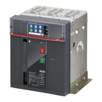
Signallings
A
B
C
D
E
F
G
H
I
The following table shows the possible signals, and their meaning:
NOTE: for the references of contacts and inputs, see the paragraph “Connections”, on page
194.
Pos. Name Description
A -
Power LED, green. The possible states are:
• Off: power supply absent.
• On fixed: power supply present.
B O 01
LED for signalling the state of contact the K3 - K7, green. The possible states are:
• Off: contact open.
• On fixed: contact closed.
C O 02
LED for signalling the state of contact the K4 - K8, green. The possible states are:
• Off: contact open.
• On fixed: contact closed.
D O 03
LED for signalling the state of the contact K5 - K9, green. The possible states are:
• Off: contact open.
• On fixed: contact closed.
E O 04
LED for signalling the state of the contact K6 - K10, green. The possible states are:
• Off: contact open.
• On fixed: contact closed.
F I 01
LED for signalling the physical state of the input H1, green
(1)
. The possible states are:
• Off: floating input.
• On fixed: input short-circuited on HC.
H I 02
LED for signalling the physical state of the input H2, green
(1)
. The possible states are:
• Off: floating input.
• On fixed: input short-circuited on HC.
G I 03
LED for signalling the physical state of the input H3, green
(1)
. The possible states are:
• Off: floating input.
• On fixed: input short-circuited on HC.
I I 04
LED for signalling the physical state of the input H4, green
(1)
. The possible states are:
• Off: floating input.
• On fixed: input short-circuited on HC.
(1)
The LED turns on and off according to the physical state of the input, without taking any account of how the
Delay parameter is set.

 Loading...