ABB | SACE Emax 2
Electronic accessories | 6 - Ekip Signalling 2K modules207 | © 2017 ABB | 1SDH001330R0002 - ECN000058721 Rev. A
Signals and inputs/outputs
A
ED
C
B
L
I
H
G
F
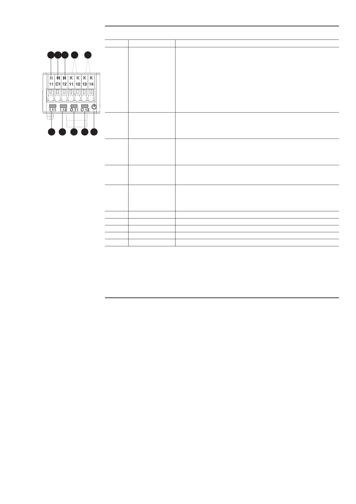
The following table shows all the signals, inputs and outputs of the module:
Pos. Name Description
A -
Power LED, green. The possible states are:
• Off: power supply absent.
• On fixed: power supply and communication with the trip unit present
(with a trip unit with the Alive LED option disabled).
• On, with one flash per second (synchronized with that of the green LED
on the trip unit): power supply and communication with trip unit present
(with a trip unit with the Alive LED option enabled).
• On, with two quick flashes per second (not synchronized with those of
the green LED on the trip unit): power supply present, and communication
with trip unit absent (for example: because of Local Bus disabled)
(1)
.
B I x1
(2)
LED for signalling the physical state of the input H x1
(2)
, green
(3)
. The
possible states are:
• Off: floating input.
• On fixed: input short-circuited on H Cx
(2)
.
C I x2
(2)
LED for signalling the physical state of the input H x2
(2)
, green
(3)
. The
possible states are:
• Off: floating input.
• On fixed: input short-circuited on H Cx
(2)
.
D O x1
(2)
LED for signalling contact K x1 - K x2
(2)
, green. The possible states are:
• Off: contact open.
• On fixed: contact closed.
E O x2
(2)
LED for signalling the state of the contact K x3 - K x4
(2)
, green. The
possible states are:
• Off: contact open.
• On fixed: contact closed.
F H x1
(2)
Input I x1.
G H Cx
(2)
Conductive part of the inputs H x1 and H x2
(2)
.
H H x2
(2)
Input I x2
(2)
.
I K x1, K x2
(2)
Output contact pin O x1
(2)
.
L K x3, K x4
(2)
Output contact pin O x2
(2)
.
(1)
The absence of communication is signalled immediately by the power LED, unlike the outputs which (except
for those programmed to be activated in the case of disconnection) are deactivated if the condition persists for
at least 8 s.
(2)
With x = 1, 2, or 3.
(3)
The LED turns on and off according to the physical state of the input, without taking any account of how the
Delay parameter is set.

 Loading...