 Loading...


Do you have a question about the ABB SACE Emax E2.2 and is the answer not in the manual?
| Rated Voltage (Ue) | Up to 690V AC |
|---|---|
| Standards | IEC 60947-2 |
| Poles | 3, 4 |
| Type | Air Circuit Breaker |
| Protection Functions | Overload, Short-circuit |
| Mounting | Fixed |
| Dimensions | Various, depending on frame size and configuration. Consult ABB documentation. |
| Weight | Various, depending on frame size and configuration. Consult ABB documentation. |
Details compliance with international standards like IEC 60947 and EC directives.
Provides criteria for selecting Emax 2 circuit-breakers based on device, standard, and characteristics.
Lists electrical specifications such as rated voltage, current, and short-circuit breaking capacity.
Outlines available basic and additional protection functions for trip units.
Lists electrical signalling, service trip units, motor operators, and mechanical accessories.
Explains how to achieve selectivity between ABB SACE circuit-breakers for fault isolation.
Lists available software tools for Emax 2 design, estimation, and thermal calculation.
Provides a list of available brochures, product notes, white papers, catalogues, and handbooks.
Introduces the five types of protection trip units for SACE Emax 2 and their functionalities.
Explains integrated functions like self-diagnosis, testing, and power control.
Describes the operator interface components and LEDs for Ekip Dip trip units.
Details protections like L, S, I, G, and their parameters for Ekip Dip.
Guides through performing LED tests, battery tests, protection tests, and opening tests.
Describes functions like Maintenance, Local Bus, Date/Time, Programmable States, and Functions.
Describes the functions, components, and navigation of the Ekip Touch interface.
Provides access to Protections, Advanced, Settings, Test, About, and Measurements menus.
Guides on modifying parameters, programming trip units, and editing pages.
Introduces touch protections and lists protections against overload, short circuit, and earth faults.
Details protections like UV, OV, VU, UF, OF, RP, Phase Sequence, Cos φ, and Synchrocheck.
Introduces Hi-Touch protections and lists protections like S2, D, UV2, OV2, UF2, OF2.
Introduces G Touch protections and lists protections like S(V), RV, RQ, OQ, OP, UP.
Introduces G Hi-Touch protections and lists protections like ROCOF, S2(V), RQ2.
Explains Gext and Rc protections and their operating principles.
Lists available measurements for trip units, including instantaneous currents and history.
Details measurements for voltage, power, frequency, and energy using Ekip Measuring modules.
Covers Hi-Touch measurements for waveforms, harmonics, and network analysis.
Guides on performing Autotest, Trip Test, Test CB, Zone Selectivity, Ekip Signalling, and Rc Test.
Explains alarm tests, self-diagnosis signals, and programming errors.
Details operating currents, voltages, and auxiliary power supply specifications.
Covers functions like Line frequency, Local/Remote, Local Bus, Harmonics, Power Controller, etc.
Lists default parameters for Ekip Touch, Hi-Touch, and G Hi-Touch trip units.
Explains the Ekip Power Controller function for load management and energy optimization.
Illustrates trip curves for available protections and trip units.
Shows tripping curves for L-I, L-S(t=k/I^2)-I, L-S(t=k)-I, and G protections.
Displays tripping curves for L-I, L-S(t=k/I^2)-I, and L-S(t=k)-I protections.
Shows tripping curves for UV, OV, VU, UF, OF, and RP protections.
Displays tripping curves for D protection.
Shows tripping curves for S(V), RV, RQ, OQ, OP, and UP protections.
Displays tripping curves for ROCOF protection.
Shows tripping curves for Rc protection.
Lists documents for Ekip Com communication modules and their integration files.
Explains Zone Selectivity, its implementation, and logic/hardware selectivity.
Details the Ekip Power Controller for load management, power limits, and energy optimization.
Describes specific protections and functions for low voltage synchronous generators.
Covers standard accessories for fixed and withdrawable circuit-breakers.
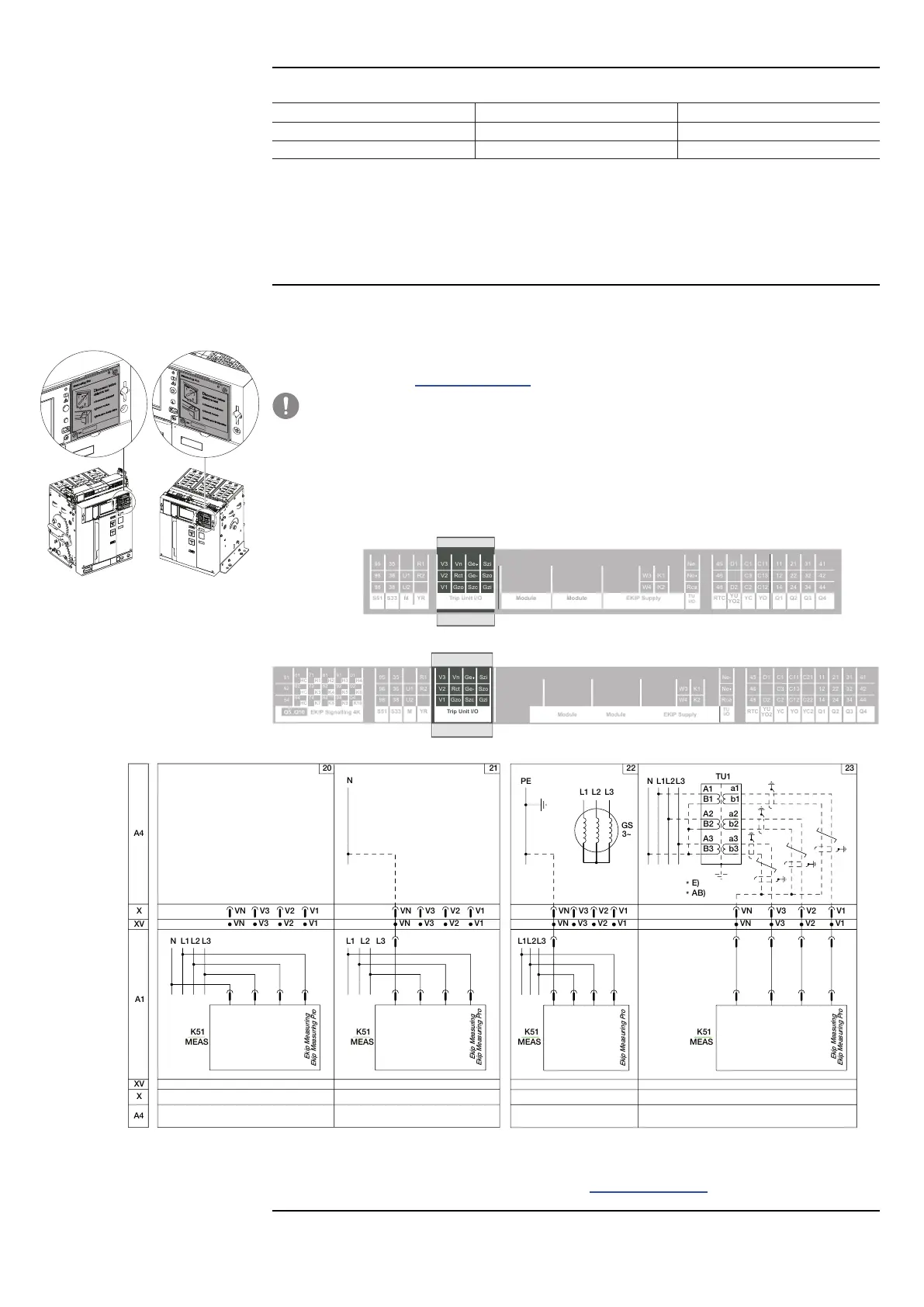
Provides general wiring diagrams for circuit-breakers and switch-disconnectors.
Shows terminal box views and differences for E1.2 and E2.2-E6.2 circuit-breakers.
Details steps for removing front cover and protections for E1.2 circuit-breakers.
Explains four types of mechanical interlocks for controlling circuit-breaker logic.
Provides step-by-step instructions for manual opening and closing operations.
Covers installation environment, temperature, weather, dust, and vibration standards.
Provides information on overall dimensions and mounting hole drilling.
Details protection degrees, dissipated power, and derating due to temperature.
Lists standard and additional accessories for circuit-breakers.
Guides on identifying faults, causes, remedies, and signals shown on the display.
Introduces the LEAP analysis program for assessing circuit-breaker health and life expectancy.
Describes ABB's PowerCare services for electrification systems.