ABB | SACE Emax 2
216 | © 2017 ABB | 1SDH001330R0002 - ECN000058721 Rev. A Electronic accessories | 9 - Ekip Com DeviceNet modules™
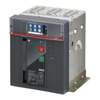
9 - Ekip Com DeviceNet modules™
Description
The Ekip Com DeviceNet™ is a communication accessory module that integrates the circuit-breaker in an
industrial remote supervision and control network.
It can be connected to a CAN network with a DeviceNet™ communication protocol, and allows you to:
• Connect the trip units as slaves to the network, with dialog functionality.
• Command opening and closing of the circuit-breaker from remote.
• Provide information on the state of the circuit-breaker (open, closed, tripped).
• If mounted on a circuit-breaker in withdrawable version, detect the connected/disconnected position.
For more details about how to access information and transmit commands to the trip unit via the module,
consult chapter "System Interface" on page 155.
Remote opening and closing of the circuit-breaker can be performed only if the circuit-breaker is equipped
with an Ekip Com Actuator module (see page 243).
For applications in which a high network reliability is necessary, the module can be installed along with the
corresponding Redundant module.
The Redundant module is identical in terms of characteristics and installation, but its wiring is different from
the non-Redundant model.
IMPORTANT: on each circuit-breaker, only one Ekip Com DeviceNet™, and only one
Ekip Com Redundant DeviceNet™ can be installed.
IMPORTANT: when the circuit-breaker is in the disconnected position, the trip unit
is disconnected from the module: in this condition, the only valid information
transmitted is:
• Connection of trip unit to Com module (Trip unit disconnected = disconnected).
• CB position (CB isolated / CB connected = CB isolated).
• Presence of com module ( = present; only valid for the module to which it is connected).
Further details are given in document 1SDH001140r0001 (Communication System
Interface for Emax 2), sections Status Global 1 [dlog], Status Accessories 1 and
Status Accessories 2.
The modules are always supplied with Ekip AUP and Ekip RTC contacts (see the chapter "16 - Other
accessories" on page 244).
Compatibility and power supply
The modules can be installed combined with Ekip Touch, Hi-Touch, G Touch, and G Hi-Touch trip units, and
require the presence of an Ekip Supply module in the first slot of the circuit-breaker terminal box.
Connections
The modules must be mounted on the terminal box of the circuit-breaker or of the fixed part of the withdrawable
circuit-breaker, in the first free slot after the Ekip Supply module.
Information on the assembly is available on the website http://www.abb.com/abblibrary/DownloadCenter/, in
particular in the kit sheet 1SDH001000r0512.
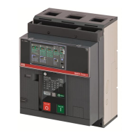
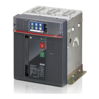
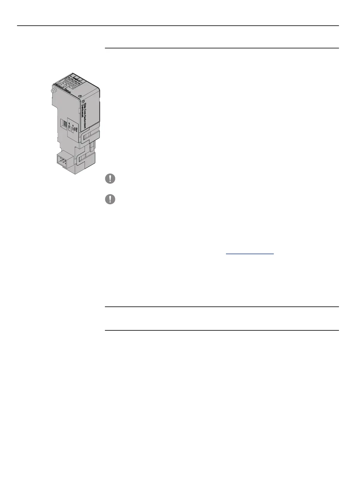
An example with an E2.2 circuit-breaker in fixed and withdrawable versions is provided to the side.
The following is a view of the terminal box of E1.2 and E2.2-E4.2-E6.2 circuit-breakers with the relevant wiring
diagram:
R2
R1
U2
U1
38
36
35
98
96
95
YRMS33S51
YO
EKIP SupplyTrip Unit I/O
Ge-
Ge
Szc
K2
K1
W4
W3
Q4Q3Q2Q1YC
YU
YO2
RTC
I/O
TU
44
42
41
34
32
31
24
22
21
14
12
11
C12
C13
C11
C2
C3
C1
D2
D1
48
46
45
Ne
Rca
Ne-
Gzi
Szo
Szi
Gzo
Rct
Vn
V1
V2
V3
Module Module
YO
01
H4
02
K5
04
K10K9
94
92
H3
9181
H2
82
K4
K8
8474
K7
K3
H1
72
7161
HC
62
64
54
52
51
EKIP SupplyModuleTrip Unit I/O
HC
K6
Ge-
Ge
Szc
K2
K1
W4
W3
R2
R1
Q4Q3Q2Q1YC2YC
YU
YO2
RTC
I/O
TU
44
42
41
34
32
31
24
22
21
14
12
11
C22
C21
C12
C13
C11
C2
C3
C1
D2
D1
48
46
45
Ne
Rca
Ne-
Gzi
Szo
Szi
Gzo
Rct
Vn
V1
V2
V3
U2
U1
38
36
35
98
96
95
YRMS33S51
EKIP Signalling 4KQ5..Q10
Module Module
HC
W7
(L)(H)
BUS 1
W8
V+ V-
194
XK7 XK71 2
193
S75I/5
*
O)
K51
COM
* L)
V+ V-
W8R
BUS 2
(H)(L)
V+
W7R
V+
V-
V-
*
V)
*
V)
TM
Ekip Com Redundant
DeviceNet
TM
A4
A3
A4
Diagrams 55 - 65
For the communication buses BUS1 and BUS2, Belden type 3084A or equivalent cables must be used.
Further information is available on page 174, or on the website http://www.abb.com/abblibrary/
DownloadCenter/, where the wiring diagram is available 1SDm000091r0001.

 Loading...