ABB | SACE Emax 2
Electronic accessories | 5 - Ekip Signalling 4K module195 | © 2017 ABB | 1SDH001330R0002 - ECN000058721 Rev. A
Connections
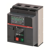
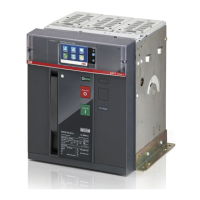
The module must be mounted directly on the Mainboard, to the left of the trip unit. The outputs and inputs of
the module are therefore accessible from the terminal box of the circuit-breaker.
Information on the assembly is available on the website http://www.abb.com/abblibrary/DownloadCenter/, in
particular in the kit sheet 1SDH001000r0516.
An example with an E2.2 circuit-breaker in fixed and withdrawable versions is provided to the side.
The wiring diagram for the module is shown below:
YO
01
H4
02
K5
04
K10K9
94
92
H3
9181
H2
82
K4
K8
8474
K7
K3
H1
72
7161
HC
62
HC
64
54
52
51
Trip Unit I/O
HC
K6
Ge-
Ge
Szc
R2
R1
Q4Q3Q2Q1YC2YC
YU
YO2
RTC
I/O
TU
43
42
41
33
32
31
23
22
21
13
12
11
C22
C21
C12
C13
C11
C2
C3
C1
D2
D1
48
46
45
Ne
Rca
Ne-
Gzi
Szo
Szi
Gzo
Rct
Vn
V1
V2
V3
U2
U1
38
36
35
98
96
95
YRMS33S51
EKIP Signalling 4KQ5..Q10
Module Module Module
EKIP Supply
K2
K1
W4
W3
2
K3
K7
K3
K7
K3
K7
XV
A4
X
X
XV
A1
A4
I 01
O 04
K51
O 01
O 02 O 03
I 02 I 03 I 04
K8
K4
K8
K4
K8
K4
K9
K5
K9
K5
K9
K5
K10
K6
K10
K6
K10
K6
H4
H3
H2
H1
HC
HC
HC
HC
H4
H4
H3
H3
H2
H2H1
H1
HC
HC
Ekip Signallin
g 4K
SIGN
HC
HC
HC
Diagram 2
Further information is available on page 174, or on the website http://www.abb.com/abblibrary/
DownloadCenter/, where the wiring diagram is available 1SDm000091r0001.
Access from the display
To configure the module the trip unit must be on.
Then, the presence of the module activates the additional menus on the display:
• In order to configure the input and output contacts.
• To display information on the module and the state of inputs and outputs.
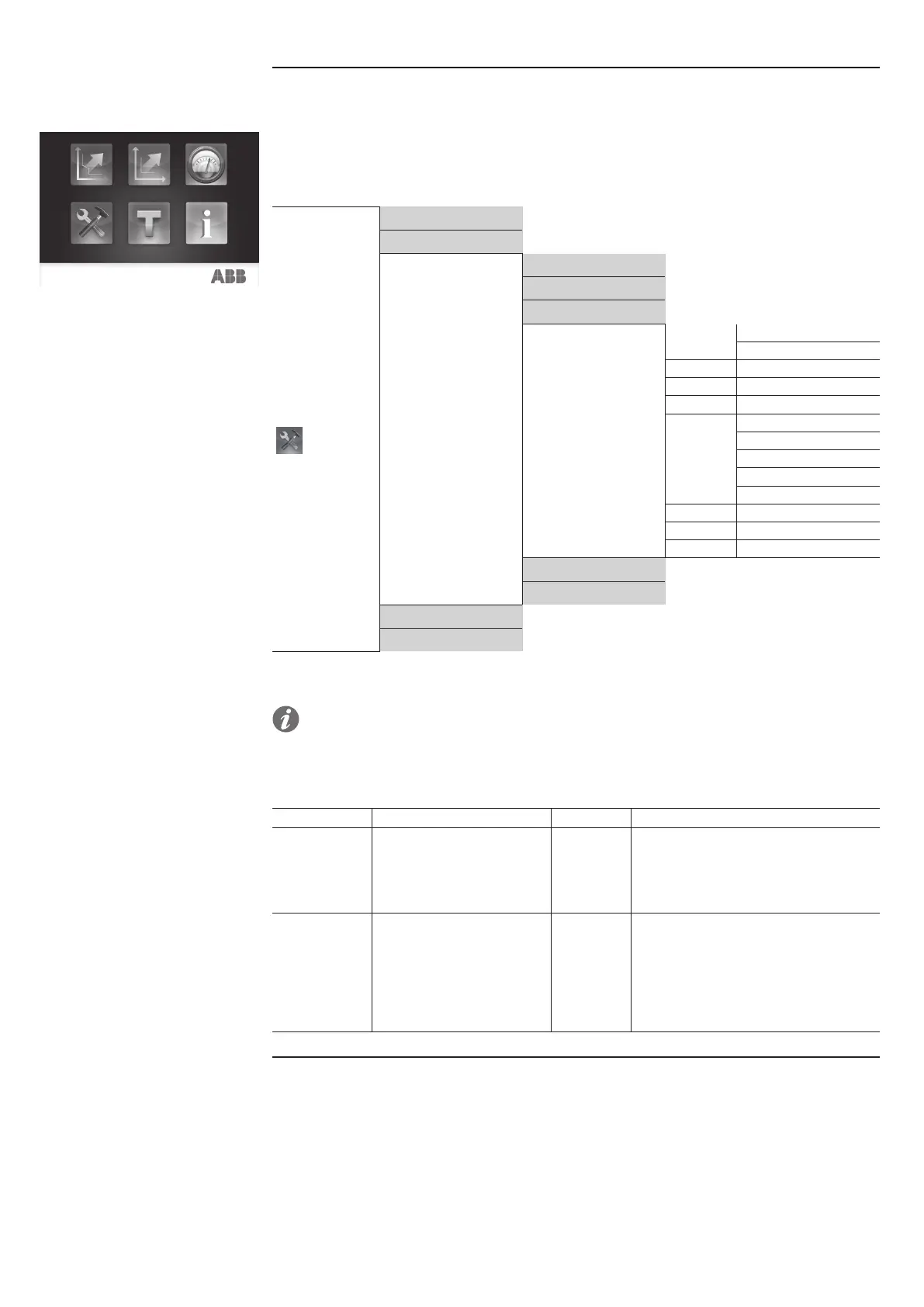
The following table shows the path for accessing the configuration parameters of the module from the display:
Settings
…
Main frequency
Modules
Local/Remote
Local Bus
…
Ekip Signalling 4K
I 01
Polarity
Delay
I 02
(1)
I 03
(1)
I 04
(1)
O 01
Signal source
Delay
Contact type
Self-latching
Min activation time
O 02
(2)
O 03
(2)
O 04
(2)
…
Functions
Power Controller
…
(1)
As the menu I 01.
(2)
As the menu O 01.
NOTE: the module can also be configured through the Ekip Connect software (see the chapter
"16 - Other accessories", and the paragraph "Ekip Connect software" on page 245).
The following table shows the configuration parameters of the inputs:
Parameter Selectable values Default Description
Polarity Active open, Active closed
Active
closed
• Active open = To be considered active,
the input must be floating.
• Active closed = To be considered
active, the input must be connected to its
reference.
Delay
0.00…100.00 s
steps of 0.01 s
0.1 s
Delay time after the input is activated
before the change of state is recognized
(if the input is reset before a time equal to
the delay has elapsed, the change of state
is not recognized). If 0.00 s is selected,
the value 300 μs is assigned to the
parameter.
Continued on the next page

 Loading...