 Loading...
Do you have a question about the Bosch Climate 5000i and is the answer not in the manual?
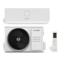
| Type | Split system |
|---|---|
| Ionizer | Yes |
| Multi-split | No |
| Display type | LED |
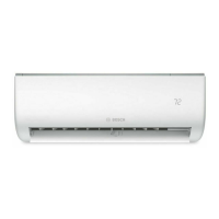
| Product color | White |
| Gas hose diameter | 9.52 mm |
| Hose length (max) | 25 m |
| Inverter technology | - |
| Liquid hose diameter | 6.35 mm |
| Refrigerating medium | R32 |
| Air conditioner functions | Cooling, Dehumidifying, Heating |
| Cooling capacity (nominal) | 12000 BTU/h |
| Refrigerating medium weight | 620 g |
| Suitable for room area up to | - m² |
| Cooling capacity in watts (max) | 4300 W |
| Cooling capacity in watts (min) | 1400 W |
| Heating capacity in watts (max) | 4400 W |
| Heating capacity in watts (min) | 1100 W |
| Cooling capacity in watts (nominal) | 3500 W |
| Cooling energy efficiency (EER, W/W) | 3.9 |
| Heating energy efficiency (COP, W/W) | 3.93 |
| Operating temperature (cooling) (T-T) | -15 - 50 °C |
| Operating temperature (heating) (T-T) | -15 - 24 °C |
| Seasonal efficiency rating (cooling) (SEER) | 8.5 |
| Heating capacity in watts (nominal) (Warmer heating season) | - W |
| Heating capacity in watts (nominal) (Average heating season) | 3810 W |
| Seasonal efficiency rating (heating) (SCOP) (Warmer heating season) | 5.8 |
| Seasonal efficiency rating (heating) (SCOP) (Average heating season) | 4.3 |
| Current | 10 A |
| AC input voltage | 220 - 240 V |
| AC input frequency | 50 Hz |
| Design load (cooling) | 3.3 kW |
| Energy efficiency scale | A+++ to D |
| Energy efficiency class (cooling) | A+++ |
| Power consumption (cooling) (max) | 1650 W |
| Power consumption (cooling) (min) | 120 W |
| Power consumption (heating) (max) | 1480 W |
| Power consumption (heating) (min) | 110 W |
| Annual energy consumption (cooling) | 136 kWh |
| Hourly energy consumption (cooling) | - kWh |
| Design load (heating) (Colder heating season) | - kW |
| Design load (heating) (Average heating season) | 2.6 kW |
| Energy efficiency class (heating) (Average heating season) | A+ |
| Annual energy consumption (heating) (Warmer heating season) | 628 kWh |
| Annual energy consumption (heating) (Average heating season) | 847 kWh |
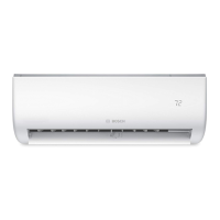
| Indoor unit type | Wall-mountable |
| Indoor unit depth | 200 mm |
| Indoor unit width | 802 mm |
| Indoor unit height | 295 mm |
| Indoor unit weight | 8700 g |
| Cooling airflow (indoor unit) | 520 m³/h |
| Indoor unit sound power level | 60 dB |
| Indoor unit noise level (low speed) | 21 dB |
| Indoor unit noise level (high speed) | 37 dB |
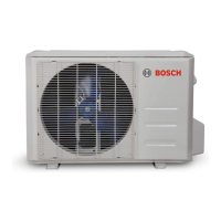
| Outdoor unit depth | 303 mm |
| Outdoor unit width | 765 mm |
| Outdoor unit height | 555 mm |
| Outdoor unit weight | 26400 g |
| Outdoor unit noise level | 55 dB |
| Cooling airflow (outdoor unit) | 2200 m³/h |
| Outdoor unit sound power level | 64 dB |