3.16 Speed governor interface
The speed governor output is used to control the speed or the power of the engine via the remote
speed controlling input provided by the speed governor.
The output from the controller can work in the following modes:
voltage mode 0 to 10 V
voltage mode 0 to 10 V with serial 10k resistor
5 V PWM mode
NOTE:
The PWM mode is designed and optimized for Caterpillar governors. Since IC-NT SW v. 1.4.4 speed
governor PWM frequency is fixed to 500 Hz.
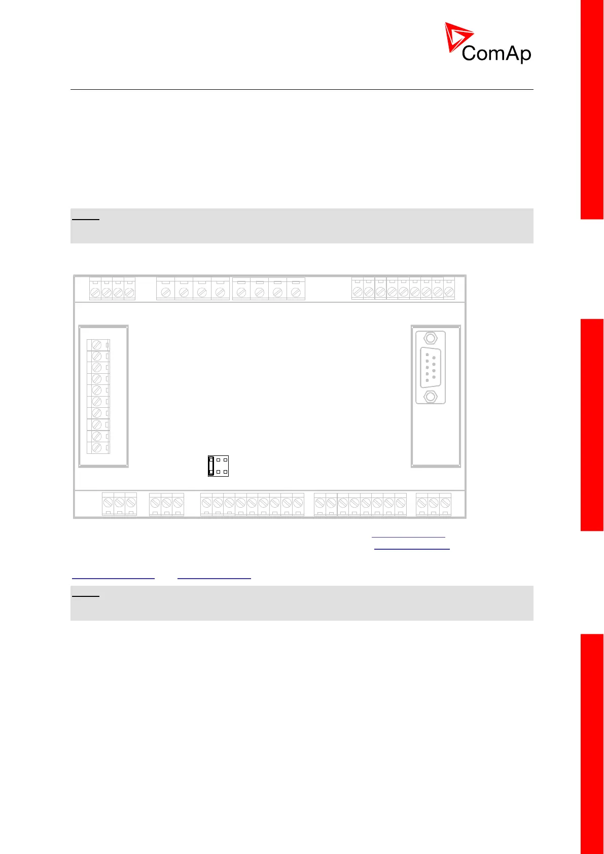
The jumpers for speed governor output mode are shown on the picture below.
The initial level of the governor output is adjustable by the setpoint Speed Gov Bias and the
characteristic (positive or negative) can be selected by the setpoint Speed Gov Char.
The active range of the output can be adapted to the governor input range by setpoints
SpeedGovLowLim and SpeedGovHiLim.
NOTE:
Some governors may evaluate input voltage out of the allowed range as a faulty condition and their
functioning may be blocked.

 Loading...