3.14.2 MCB special requirements
SPtM only
1. If a contactor is used on the MCB position, it is recommended that the wiring be provided in
such a way that the contactor will be normally closed and will open if the MCB Close/Open
closes. This behaviour is called “negative logic” and can be adjusted by the setpoint MCB
Logic. The negative logic will prevent accidental opening of the MCB when the controller is
switched off.
2. If a contactor is used on the MCB position, it will open itself immediately after the mains have
failed, because it will lose power for the coil. That is why the following adjustment is necessary
to prevent triggering the MCB fail alarm: MCB Opens On = MAINSFAIL, Mains V Del 1.
3. If a 230 V motor driven circuit breaker is used on the MCB position and an undervoltage coil is
not fitted, it is not possible to open the breaker after the mains have failed, because there is no
power for the motor drive until the gen-set is started and providing voltage. Adjusting the
setpoint MCB Opens On = GEN RUN will prevent triggering the MCB fail alarm.
3.15 AVR interface
The AVR output is used to control the voltage or power factor of the generator via the remote voltage
adjust input provided by the AVR.
The output from the controller is a 5V PWM that is designed to be used together with the IG-AVRi
module. The AVRi module provides galvanic separation of the controller from the generator and PWM
to voltage conversion, which is needed for most AVRs. The output from the IG-AVRi module is
available as positive, negative or symmetric. The output voltage range is adjustable by a trimmer
located on the module.
The initial level of the AVR output is adjustable by the setpoint AVRi Bias.
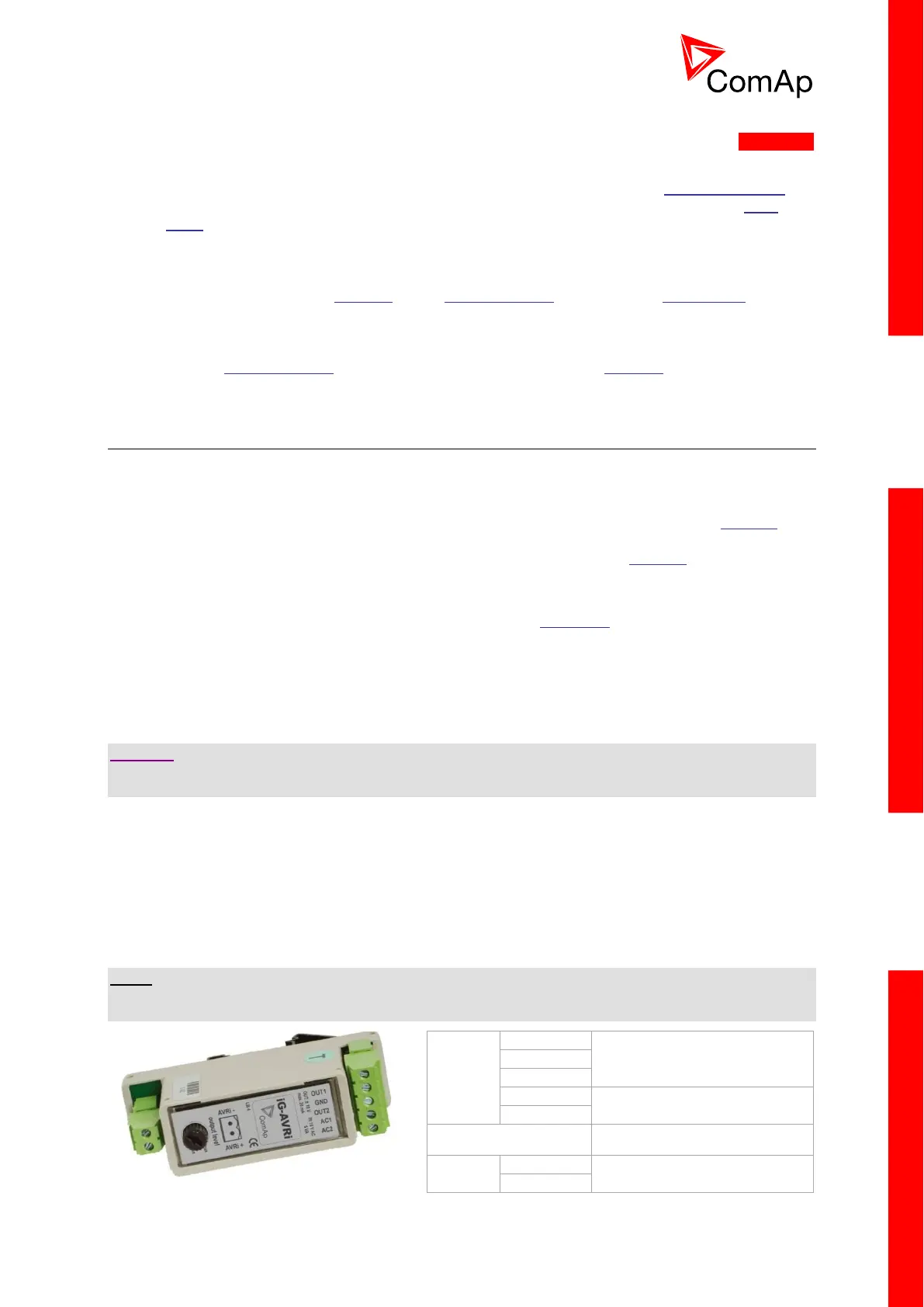
3.15.1 IG-AVRi
Automatic voltage Regulator interface is used for volt/PF control adjustment through galvanic
separated inputs and outputs.
CAUTION:
Refer each time to the corresponding AVR manual before connecting the interface. IG-AVRi-TRANS
(AC power supply for AVRi) has to be supplied from gen-set voltage.
AVRi output can be connected as symmetrical: OUT1-OUT2 or unsymmetrical OUT1-GND or OUT2-
GND.
- The potentiometer on the AVRi defines maximum OUT1, OUT2 voltage range.
- Use symmetrical (OUT1, OUT2) AVRi output to connect the AVRi to AVR auxiliary voltage
input.
- Use unsymmetrical output if an external AVR potentiometer has to be replaced with AVRi.
- AVRi output voltage should change the generator voltage typically in the range ± 10% of the
Nominal voltage.
NOTE:
IG-AVRi is not included in the standard package with the controller.
IG-AVRi TRANS/LV is a power supply unit for IG-AVRi; it is not included with the IG-AVRi package.

 Loading...