NOTE:
IT IS NECESSARY TO ENSURE THAT THE POTENTIAL DIFFERENCE BETWEEN THE GENERATOR CURRENT COM
TERMINAL AND THE BATTERY “-” TERMINAL IS MAXIMUM ± 2V. THEREFORE, IT IS STRONGLY RECOMMENDED TO
INTERCONNECT THESE TWO TERMINALS TOGETHER.
CAUTION:
WHEN YOU ARE USING INTELICOMPACT
NT
HW VERSION 1.3 OR NEWER IT IS NECESSARY TO UPGRADE THE
FIRMWARE TO IC-NT-1.4.3 OR NEWER.
Since HW version 1.3 the InteliCompact
NT
measures current with reversed polarity. It is not
recommended to switch wiring at the current transformer side. To fix this error use FW IC-NT-1.4.3 or
newer.
3.10 Speed measurement
The engine speed can be measured either from the generator frequency or from a magnetic pickup. If
an EFI engine is configured, the engine speed is obtained from the ECU.
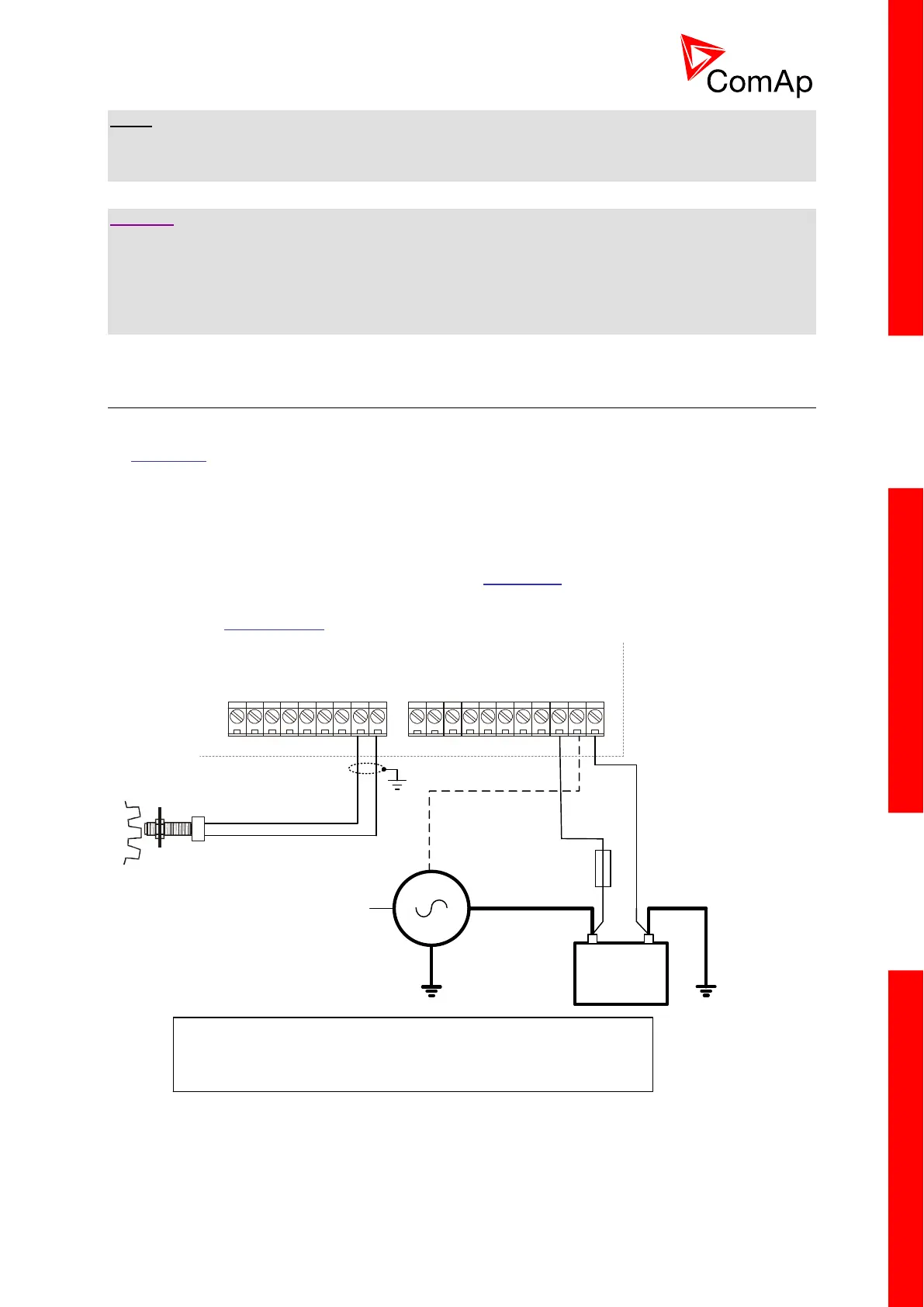
3.10.1 Pickup
A magnetic speed sensor (pickup) is the most common method of engine speed measurement. To
use this method, mount the pickup opposite to the engine flywheel, connect the cable to the controller
as shown on the picture below and adjust the setpoint Gear Teeth according to the number of teeth on
the flywheel.
See the chapter Technical data for details about the pickup input parameters.
+
D+
COM
RPM
-
W
D+ (L)
+
-
Pickup
Charging alternator
RPM measurement from the pickup.
D+ terminal from the charging alternator can be used as additional signal for
detection of running engine.
T2A

 Loading...