InteliCompact
NT
, SW version 2.1
InteliCompact-NT-2.1-Reference Guide.pdf, ©ComAp – May 2015
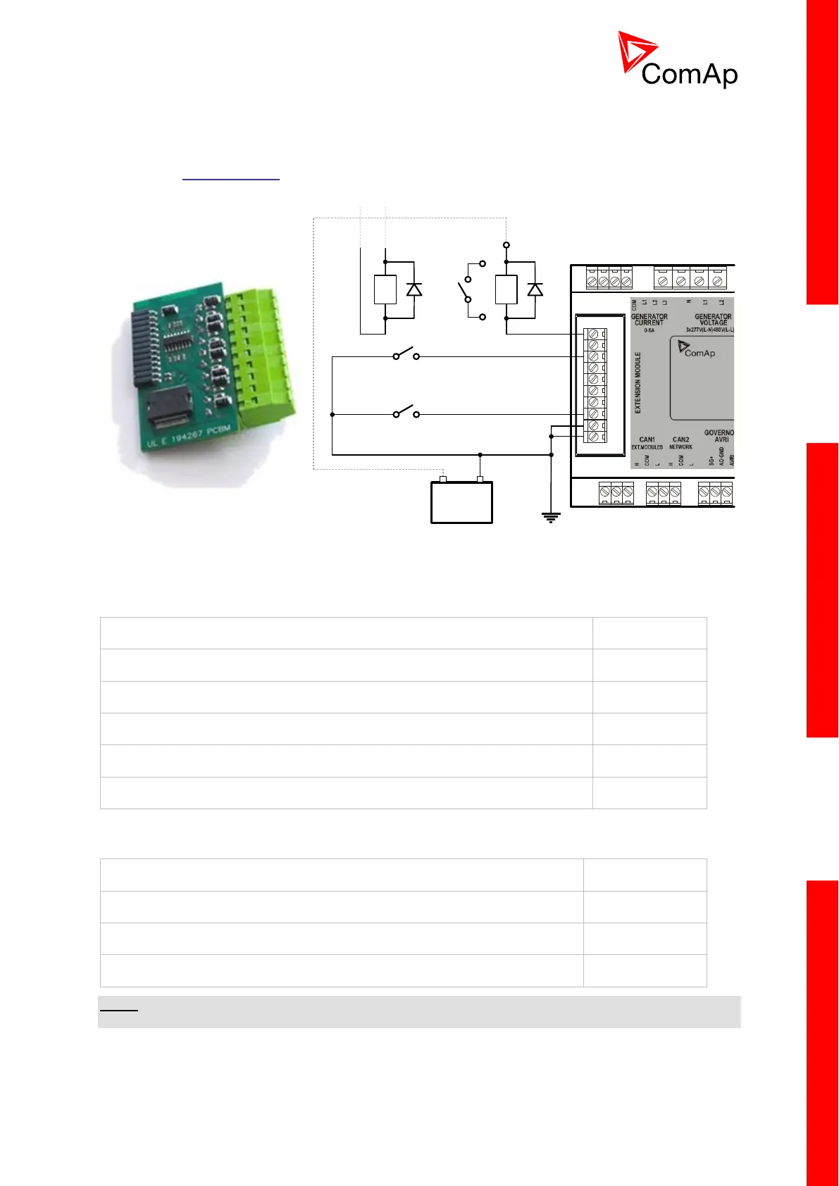
To insert the module, you must open the cover first (use a screwdriver to open) and then insert the
module into the slot. Once you have inserted it, the module will snap under the plastic teeth. It is
supposed to be installed permanently. Should you need to remove it, the safest way is to remove the
entire back cover and then remove the module manually. Installing the IL-NT BIO8 module is similar to
installing the RS 232 module. The difference is that module fits into the “extension module” slot and
after installing the IL-NT BIO8 you do not put the small cover back.
BATT-
BATT-
BIO1
BIO2
BIO3
BIO4
BIO5
BIO6
BIO7
BIO8
IN
IN
OUT
K2
K21
K11
SW1
BATT+
REL
K1
+
-
BATTERY
Technical details:
IL-NT BIO8 plugs into the InteliCompact
NT
controller EXTENSION MODULE port.
8 dedicated pins of the plug-in card’s terminal can be configured as binary inputs or outputs.
BINARY INPUTS
Voltage level for close contact indication (Logical 1)
Voltage level for open contact indication (Logical 0)
Max voltage level for open contact indication
BINARY OPEN COLLECTOR OUTPUTS
Maximum switching common current
Maximum switching voltage
NOTE:
Binary inputs are not galvanically isolated.

 Loading...