CHAPTER 5: SETTINGS
469 MOTOR MANAGEMENT RELAY – INSTRUCTION MANUAL 5–89
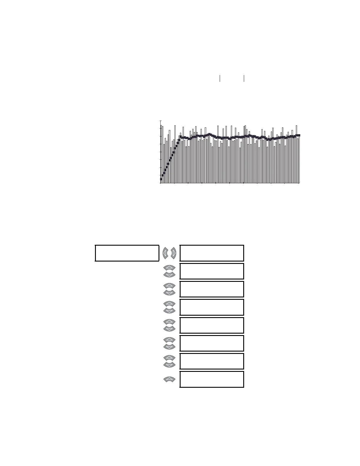
period. The average value of the buffer is calculated and stored as the new demand value
every minute. Demand for real and reactive power is only positive quantities (+kW and
+kvar).
(EQ 5.12)
where: N = programmed demand period in minutes
n = time in minutes.
FIGURE 5–19: Rolling Demand (15 Minute Window)
5.12.4 Pulse Output
PATH: SETTINGS ZV S11 MONITORING ZV PULSE OUTPUT
Demand
1
N
---
Average
N
n 1=
N
∑
=
808717A1.CDR
TIME
0
20
40
60
80
100
120
140
160
t=0 t+10 t+20 t+30 t+40 t+50 t+60 t+70 t+80 t+90 t+100
MAGNITUDE
PULSE [
POS kWh PULSE
OUTPUT
Range: Off, Alarm, Auxiliary2,
Auxiliary3
MESSAGE
POS kWh PULSE
OUTPUT
Range: 1 to 50000 kWh in steps of 1
MESSAGE
POS kvarh PULSE
OUT
Range: Off, Alarm, Auxiliary2,
Auxiliary3
MESSAGE
POS kvarh PULSE
OUT
Range: 1 to 50000 kvarh in steps of 1
MESSAGE
NEG kvarh PULSE
OUT
Range: Off, Alarm, Auxiliary2,
Auxiliary3
MESSAGE
NEG kvarh PULSE
OUT
Range: 1 to 50000 kvarh in steps of 1
MESSAGE
RUNNING TIME
PULSE
Range: Off, Alarm, Auxiliary2,
Auxiliary3
MESSAGE
RUNNING TIME
PULSE
Range: 1 to 50000 s in steps of 1
 Loading...