5–100 469 MOTOR MANAGEMENT RELAY – INSTRUCTION MANUAL
CHAPTER 5: SETTINGS
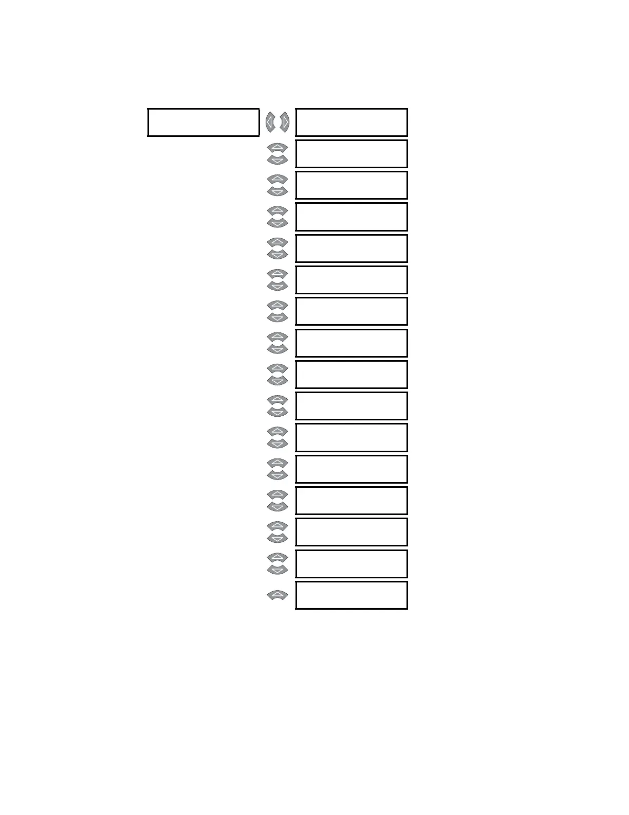
5.14.3 Fault Setup
PATH: SETTINGS ZV S13 469 TESTING ZV FAULT SETUP
The values entered under Fault Values will be substituted for the measured values in the
469 when the simulation mode is “Simulate Fault”.
FAULT [
FAULT CURRENT
PHASE A: 0.00 x
Range: 0.00 to 20.00 x CT in steps of
0.01
MESSAGE
FAULT CURRENT
PHASE B: 0.00 x
Range: 0.00 to 20.00 x CT in steps of
0.01
MESSAGE
FAULT CURRENT
PHASE C: 0.00 x
Range: 0.00 to 20.00 x CT in steps of
0.01
MESSAGE
FAULT GROUND
CURRENT: 0.0 A
Range: 0.0 to 5000.0 A in steps of 0.1
MESSAGE
FAULT VOLTAGES
VLINE: 1.00 x
Range: 0.00 to 1.10 x RATED in steps of
0.01
MESSAGE
FAULT CURRENT
LAGS VOLTAGE: 0°
Range: 0 to 359° in steps of 1
MESSAGE
FAULT DIFF AMPS
IDIFF: 0.00 x CT
Range: 0.00 to 1.10 x RATED in steps of
0.01
MESSAGE
FAULT STATOR
RTD TEMP: 40°C
Range: –50 to 250°C in steps of 1
MESSAGE
FAULT BEARING
RTD TEMP: 40°C
Range: –50 to 250°C in steps of 1
MESSAGE
FAULT OTHER
RTD TEMP: 40°C
Range: –50 to 250°C in steps of 1
MESSAGE
FAULT AMBIENT
RTD TEMP: 40°C
Range: –50 to 250°C in steps of 1
MESSAGE
FAULT SYSTEM
FREQUENCY: 60.0
Range: 45.0 to 70.0 Hz in steps of 0.1
MESSAGE
FAULT ANALOG
INPUT 1: 0%
Range: 0 to 100% in steps of 1
MESSAGE
FAULT ANALOG
INPUT 2: 0%
Range: 0 to 100% in steps of 1
MESSAGE
FAULT ANALOG
INPUT 3: 0%
Range: 0 to 100% in steps of 1
MESSAGE
FAULT ANALOG
INPUT 4: 0%
Range: 0 to 100% in steps of 1
 Loading...