7–8 469 MOTOR MANAGEMENT RELAY – INSTRUCTION MANUAL
CHAPTER 7: TESTING
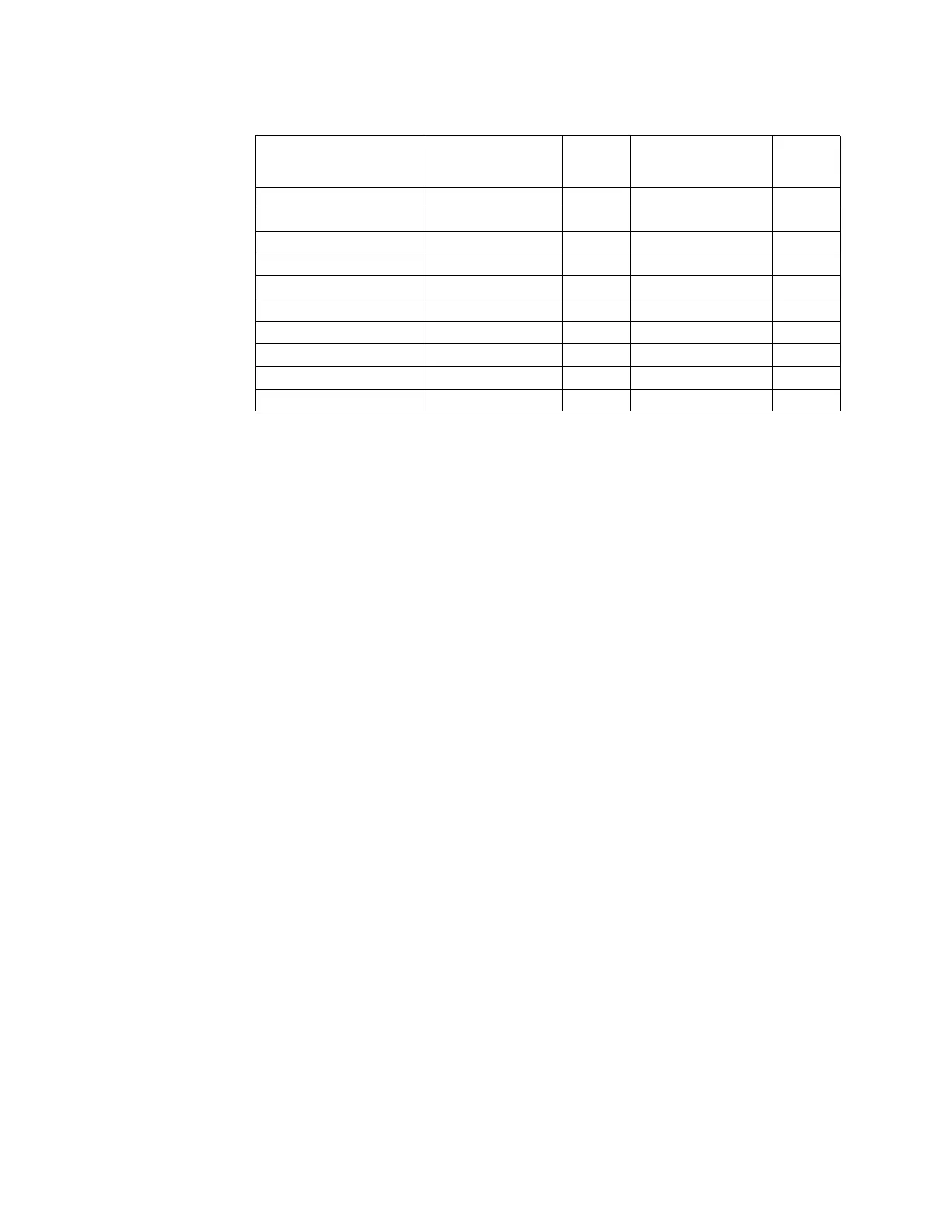
A1 STATUS ZV DIGITAL INPUTS
7.2.7 Analog Inputs and Outputs
The 469 specification for analog input and analog output accuracy is ±1% of full scale.
Perform the steps below to verify accuracy. Verify the Analog Input +24 V DC with a
voltmeter.
4 to 20 mA Analog Input
Z Alter the following settings:
S12 ANALOG I/O ZV ANALOG INPUT1 Z ANALOG INPUT1: “4-20 mA”
S12 ANALOG I/O ZV ANALOG INPUT1 ZV ANALOG INPUT1 MINIMUM: “0”
S12 ANALOG I/O ZV ANALOG INPUT1 ZV ANALOG INPUT1 MAXIMUM: “1000” (repeat this
value for Analog Inputs 2 to 4)
Analog output values should be ±0.2 mA on the ammeter. Measured analog input
values should be ±10 units.
Z Force the analog outputs using the following settings:
S13 TESTING ZV TEST ANALOG OUTPUT Z FORCE ANALOG OUTPUTS FUNCTION:
“Enabled”
S13 TESTING ZV TEST ANALOG OUTPUT ZV ANALOG OUTPUT 1 FORCED VALUE: “0%”
(enter desired value in percent; repeat for Analog Outputs 2 through 4)
Z Verify the ammeter readings as well as the measured analog input
readings.
For the purposes of testing, the analog input is fed in from the analog
output (see FIGURE 7–1: Secondary Injection Test Setup on page 7–2).
Z View the measured values in:
INPUT EXPECTED
STATUS (SWITCH
OPEN)
PASS /
FAIL
EXPECTED
STATUS (SWITCH
CLOSED)
PASS /
FAIL
ACCESS Open Shorted
TEST Open Shorted
STARTER STATUS Open Shorted
EMERGENCY RESTART Open Shorted
REMOTE RESET Open Shorted
ASSIGNABLE INPUT 1 Open Shorted
ASSIGNABLE INPUT 2 Open Shorted
ASSIGNABLE INPUT 3 Open Shorted
ASSIGNABLE INPUT 4 Open Shorted
TRIP COIL SUPERVISION No Coil Coil

 Loading...