CHAPTER 3: INSTALLATION
469 MOTOR MANAGEMENT RELAY – INSTRUCTION MANUAL 3–25
The source computer/PLC/SCADA system should have similar transient protection devices
installed, either internally or externally, to ensure maximum reliability. Ground the shield at
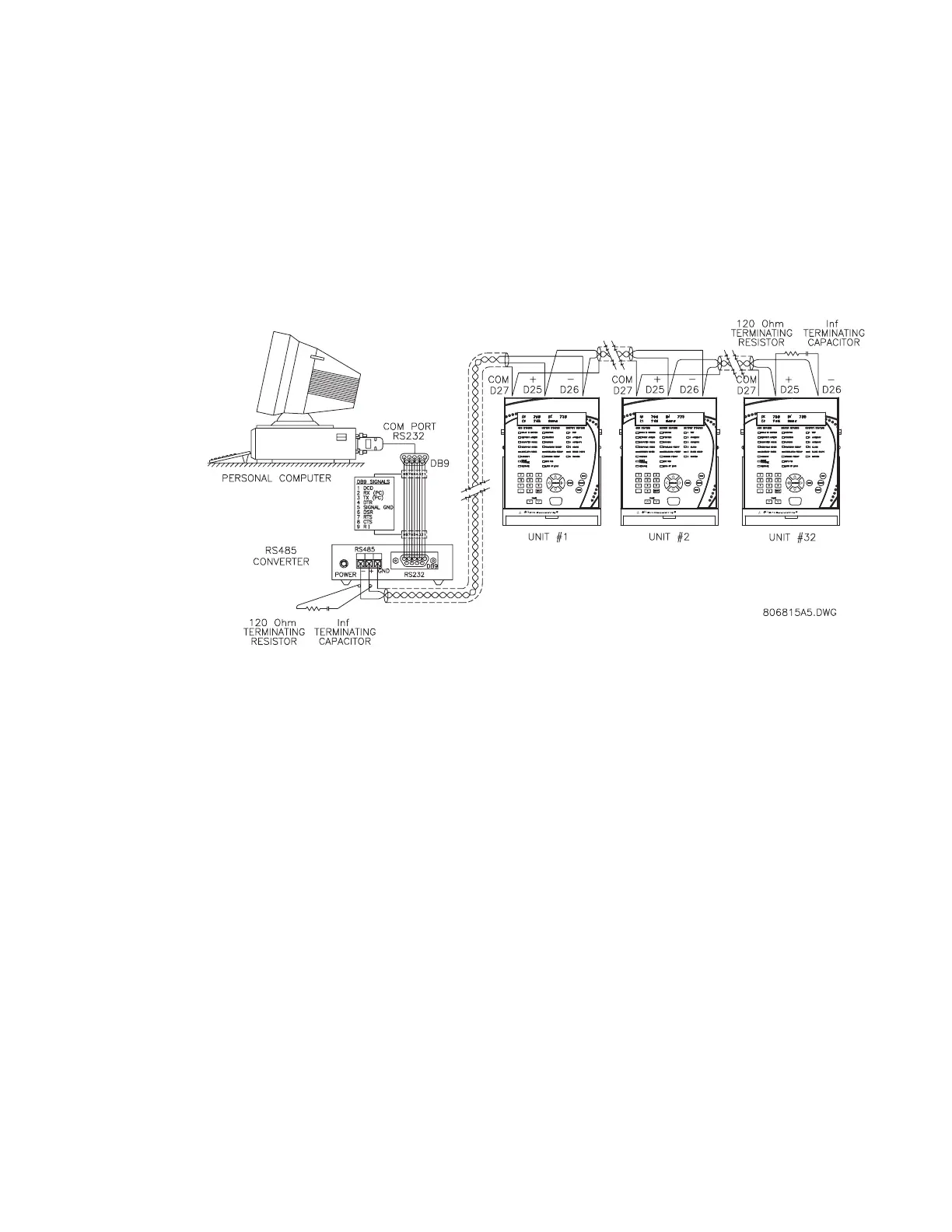
one point only, as shown in the figure below, to avoid ground loops.
Correct polarity is also essential. The 469s must be wired with all the ‘+’ terminals
connected together and all the ‘–’ terminals connected together. Each relay must be daisy-
chained to the next one. Avoid star or stub connected configurations. The last device at
each end of the daisy chain should be terminated with a 120 Ω ¼-watt resistor in series
with a 1 nF capacitor across the ‘+’ and ‘–’ terminals. Observing these guidelines provides a
reliable communication system immune to system transients.
FIGURE 3–27: RS485 Communications Wiring
3.2.13 Dielectric Strength
It may be required to test a complete motor starter for dielectric strength (“flash” or “hipot”)
with the 469 installed. The 469 is rated for 1.9 kV AC for 1 second, or 1.6 kV AC for 1 minute
(per UL 508) isolation between relay contacts, CT inputs, VT inputs, trip coil supervision, and
the safety ground terminal G12. Some precautions are required to prevent damage to the
469 during these tests.
Filter networks and transient protection clamps are used between control power, trip coil
supervision, and the filter ground terminal G11. This is intended to filter out high voltage
transients, radio frequency interference (RFI), and electromagnetic interference (EMI). The
filter capacitors and transient suppressors may be damaged by continuous high voltage.
Disconnect the filter ground terminal G11 during testing of control power and trip coil
supervision. The CT inputs, VT inputs, and output relays do not require any special
precautions. Low voltage inputs (less than 30 V), RTDs, analog inputs, analog outputs,
digital inputs, and RS485 communication ports are not to be tested for dielectric strength
under any circumstance (see below).
 Loading...