CHAPTER 3: INSTALLATION
469 MOTOR MANAGEMENT RELAY – INSTRUCTION MANUAL 3–19
In addition, the +24 V DC switch supply is brought out for control power of an inductive or
capacitive proximity probe. The NPN transistor output could be taken to one of the
assignable digital inputs configured as a counter or tachometer. Refer to Specifications on
page 2–6 for maximum current draw from the +24 V DC switch supply.
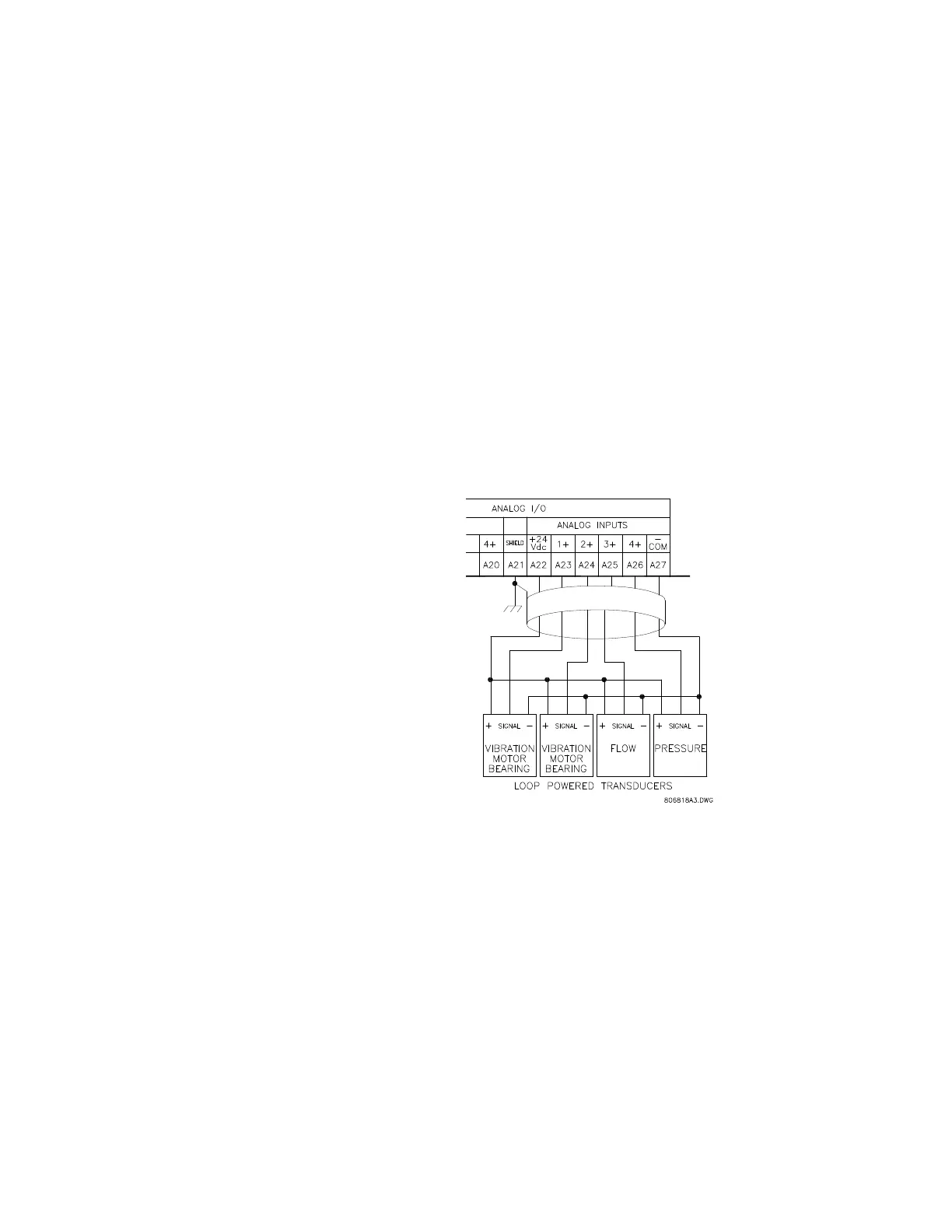
3.2.7 Analog Inputs
The 469 provides terminals for four 0 to 1mA, 0 to 20mA, or 4 to 20mA current input signals
(field programmable). This current signal can be used to monitor external quantities such
as vibration, pressure, or flow. The four inputs share one common return. Polarity of these
inputs must be observed for proper operation The analog input circuitry is isolated as a
group with the analog output circuitry and the RTD circuitry. Only one ground reference
should be used for the three circuits. Transorbs limit this isolation to ±36 V with respect to
the 469 safety ground.
In addition, the +24 V DC analog input supply is brought out for control power of loop
powered transducers. Refer to Specifications on page 2–6 for maximum current draw from
this supply.
FIGURE 3–21: Loop Powered Transducer Connection
3.2.8 Analog Outputs
The 469 provides 4 analog output channels which may be ordered to provide a full-scale
range of either 0 to 1 mA (into a maximum 10 kΩ impedance) or 4 to 20 mA (into a
maximum 1200 Ω impedance). Each channel can be configured to provide full-scale
output sensitivity for any range of any measured parameter.
As shown in FIGURE 3–12: Typical Wiring Diagram on page 3–11, these outputs share one
common return. Polarity of these outputs must be observed for proper operation. Shielded
cable should be used, with only one end of the shield grounded, to minimize noise effects.
The analog output circuitry is isolated as a group with the Analog Input circuitry and the
RTD circuitry. Only one ground reference should be used for the three circuits. Transorbs
limit this isolation to ±36 V with respect to the 469 safety ground.

 Loading...