7–4 469 MOTOR MANAGEMENT RELAY – INSTRUCTION MANUAL
CHAPTER 7: TESTING
7.2.3 Ground and Differential Accuracy Test
The 469 specification for differential current and 1 A/5 A ground current input accuracy is
±0.5% of 1 × CT for the 5 A input and 0.5% of 5 × CT for the 1 A input. Perform the steps
below to verify accuracy.
5A Input
Z Alter the following settings:
S2 SYSTEM SETUP Z CURRENT SENSING ZV GROUND CT: “5A Secondary”
S2 SYSTEM SETUP Z CURRENT SENSING ZV GROUND CT PRIMARY: “1000 A”
S2 SYSTEM SETUP Z CURRENT SENSING ZV PHASE DIFFERENTIAL CT: “5A Secondary”
S2 SYSTEM SETUP Z CURRENT SENSING ZV PHASE DIFFERENTIAL CT PRIMARY: “1000 A”
Measured values should be ±5A.
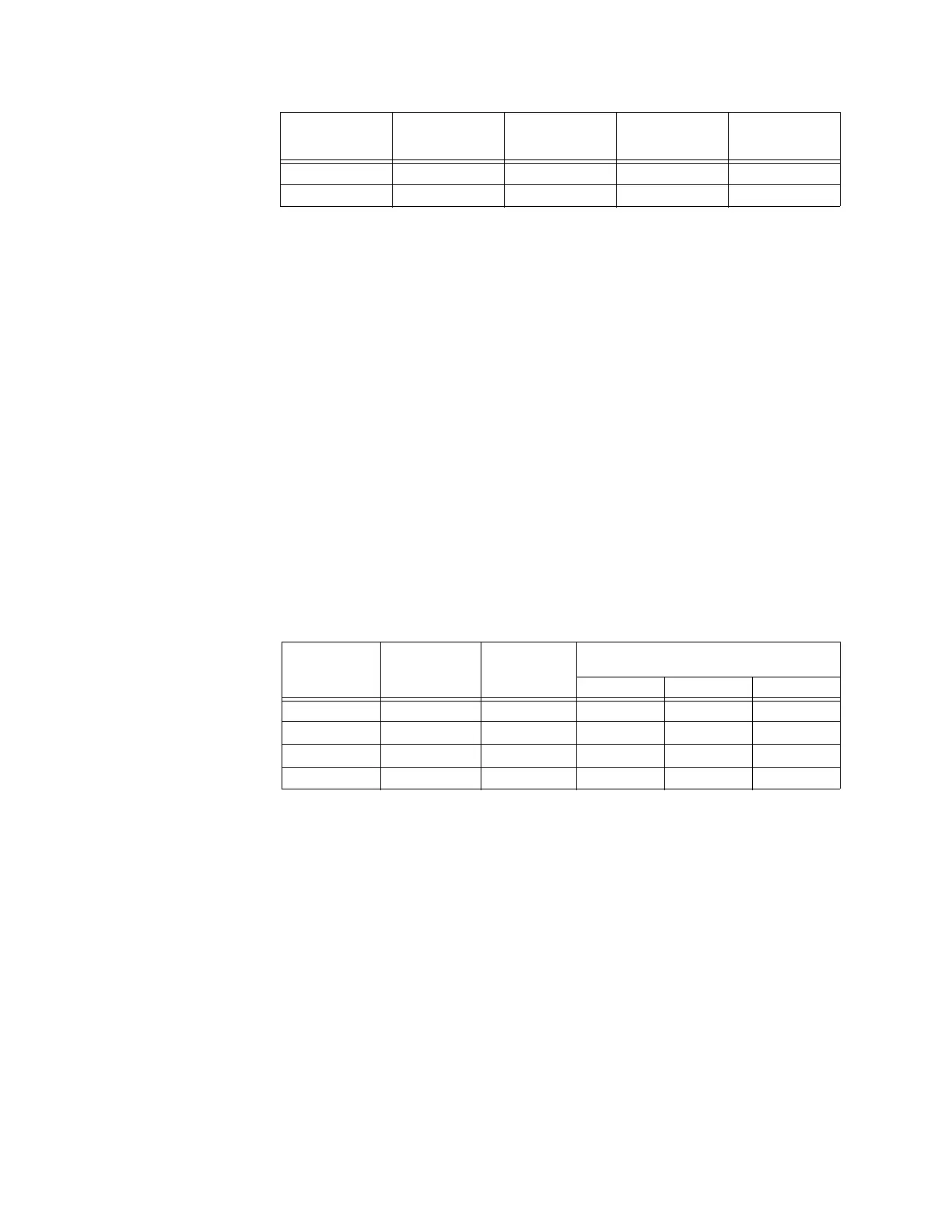
Z Inject the values shown in the table below into one phase only.
Z Verify accuracy of the measured values.
Z View the measured values in:
A2 METERING DATA Z CURRENT METERING
1A Input
Z Alter the following settings:
S2 SYSTEM SETUP Z CURRENT SENSING ZV GROUND CT: “1A Secondary”
S2 SYSTEM SETUP Z CURRENT SENSING ZV GROUND CT PRIMARY: “1000 A”
S2 SYSTEM SETUP Z CURRENT SENSING ZV PHASE DIFFERENTIAL CT: “1A Secondary”
S2 SYSTEM SETUP Z CURRENT SENSING ZV PHASE DIFFERENTIAL CT PRIMARY: “1000 A”
Measured values should be ±25 A.
Z Inject the values shown below into one phase only.
Z Verify accuracy of the measured values.
Z View the measured values in:
200 V 2000 V
270 V 2700 V
APPLIED
LINE-NEUTRAL
VOLTAGE
EXPECTED
VOLTAGE
READING
MEASURED
VOLTAGE A-N
MEASURED
VOLTAGE B-N
MEASURED
VOLTAGE C-N
INJECTED
CURRENT
5 A UNIT
EXPECTED
CURRENT
READING
MEASURED
GROUND
CURRENT
MEASURED DIFFERENTIAL
CURRENT
PHASE A PHASE B PHASE C
0.5 A 100 A
1.0 A 200 A
2.5 A 500 A
5.0 A 1000 A

 Loading...